logo elektroda
logo elektroda
X
logo elektroda

No AP anymore flashing OpenBeken on an SM-SO301-U power strip with CB3S (BK7231N) chip

tlpelektroda 1701 34
ADVERTISEMENT
  • #31 21244362
    tlpelektroda
    Level 2  
    Yes, all my older power strips were flashed with and running Tasmota, including the one that started dying recently, which is what prompted me to order new ones that I found all now have the CB3S chip. Of the 4 Tasmota strips -- 3 are still running currently and in different rooms -- I've never had any problem with them receiving and transmitting to and from the router AP signal. Nor with any of the numerous other little IOT devices I have running in various rooms, all communicating happily with the same 2.4GHz network AP as this device I've first found the first signal problem with.

    In fact, I pulled up the config pages on the existing running Tasmota strips to look at their GPIO mappings, as a guide maybe to how I might map the CB3S pins in these strips if I can get one working. The Tasmota strips are all fine and responsive, and one is right next to where I was testing the now-working OBK power strip, which couldn't see the AP at all. The OBK strip is definitely the odd man out.

    So this would seem to all lead back to the antenna, or something about the receptivity, on this device, wouldn't it? Is the antenna in the CB3S just an otherwise lifeless piece of metal, or does it have some sort of gain or amplifier or some kind of carrier current connected to it, something that might be causing it not to either receive or transmit at full strength, something that might be programmable or settable even maybe? I obviously don't know much about antennas and RF transmission/reception.

    hartzell wrote:
    >>21244297 Is your older power strip flashed with Tasmota? If so, you could bring it near the AP and see what the signal strength is, then move it away a bit and check, and a bit further, and ...

    Not sure what it'll tell us, but it might be informative.
  • ADVERTISEMENT
  • #32 21244364
    divadiow
    Level 34  
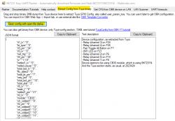
    The pin assignments are extractable from the factory fw using Easy Flasher
    Screenshot of Easy Flasher software for extracting configuration from Tuya devices.

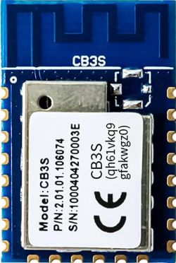
    Regarding RF - how is the physical state of the CB3S? Are there any scratches across the aerial at the top of the module that may mean most of it is severed?

    CB3S module with visible label and markings.

    Are there any minute solder whiskers between any of the contacts around the module? Have you inspected the module with a macro lens or magnifying glass for signs of damage?

    You could start the process again with one of your other new CB3S power strips...
  • ADVERTISEMENT
  • #33 21245589
    tlpelektroda
    Level 2  
    This is so awesome @divadiow, thanks for pointing it out! May I ask did this particular pin assignment layout you reproduce here come from the fw binary I sent you? Since I don't have Easy Flasher (unless I swallow hard and set this up on Window$ somehow, or install mono on my various linux boxen and try to run it etc), do you happen to know how this could be manually extracted from the fw binary? I guess I could start with a hex editor, if it's obvious and laid out contiguously in the binary, by searching for it. Or I guess I could just look at the code for EF and just replicate that. But super cool to know it can be found in the binary, thank you!
    divadiow wrote:
    The pin assignments are extractable from the factory fw using Easy Flasher
    Screenshot of Easy Flasher software for extracting configuration from Tuya devices.


    Regarding the antenna, I took a magnifying glass to it and didn't see anything obvious, although you can only see it on the front side of the CB3S PCB on this device, like in your picture, not from the back/underside, so it's hard to tell. It's possible that I damaged part of it from my solder of the top left CEN pin that's right at the base of it, but I didn't see anything obvious there too, except a bit of the excess metal from the solder joint kind of arcs over it a little. I wonder if the metal interference from the solder could cause it. I looked at Tuya's data sheet for the CB3S and discovered some potentially interesting info to people who know more about this than I (which isn't a high bar).  Like for example, that the "CB3S uses the PCB antenna with a gain of 1.3 dBi." And that they recommend keeping it clear of any metal parts within 15mm of it -- which is definitely violated by the upper pins on the chip itself -- and that no metal parts should be under an imaginary dome of circular arc of diameter 3cm etc.. As for that dome area being clear, as they say here in NYC, fuhgeddaboudit!
    So I think for now, unless you know some way I can verify and/or configure whether this chip's antenna is running with a gain of 1.3dBi or otherwise meeting its self-declared "Wi-Fi receiving performance" specs, I think I'll turn to the other strips I have to see if I can compare/duplicate/eliminate this phenomenon.
    divadiow wrote:

    Regarding RF - how is the physical state of the CB3S? Are there any scratches across the aerial at the top of the module that may mean most of it is severed?

    CB3S module with visible label and markings.

    Are there any minute solder whiskers between any of the contacts around the module? Have you inspected the module with a macro lens or magnifying glass for signs of damage?

    You could start the process again with one of your other new CB3S power strips...
  • ADVERTISEMENT
  • #34 21245595
    divadiow
    Level 34  
    tlpelektroda wrote:
    May I ask did this particular pin assignment layout you reproduce here come from the fw binary I sent you?

    yes, it did.
    tlpelektroda wrote:
    do you happen to know how this could be manually extracted from the fw binary?

    I guess it's all possible, but not sure how this could be tackled immediately. The code that does it would be buried in here somewhere I guess; https://github.com/search?q=repo%3Aopenshwprojects%2FBK7231GUIFlashTool+extract&type=code

    tlpelektroda wrote:
    except the excess metal from the solder joint kind of arcs over it a little

    goes near or actually arcs, making contact with the RF shield?
    tlpelektroda wrote:
    I wonder if the metal interference from the solder could cause it

    can't say I've noticed module clearance issues to have this effect on a conversion to OpenBeken, and presumably it *should* work.

    I guess the ultimate thing would be to remove the CB3S and play with it out of the device, see if the symptoms are the same.

    Added after 2 [minutes]:

    config for eventual import into working device:

    Code: JSON
    Log in, to see the code
  • #35 21245601
    tlpelektroda
    Level 2  
    thanks for the link on this!
    divadiow wrote:
    The code that does it would be buried in here somewhere I guess; https://github.com/search?q=repo:openshwprojects/BK7231GUIFlashTool extract&type=code


    it kind of 'arcs near'. The solder kind of wicked up when it was hot I guess and kind of bends up from the pin such that the wire bends forward over a little in the direction of the PCB antenna
    divadiow wrote:

    goes near or actually arcs, making contact with the RF shield?


    yes, but that would be overly ambitious for my skill level -- I looked at some postings where people remove the CB3S chip and swap in an ESP chip. I have enough trouble making a solder joint on a single pin not messy, never mind 22 pins simultaneously set in a PCB... but good idea for my aspirations someday lol
    divadiow wrote:
    I guess the ultimate thing would be to remove the CB3S and play with it out of the device, see if the symptoms are the same.


    Added after 3 [minutes]:

    ah thank you! I saw something in Elektroda posts on how you load/import/export configs like this, into OpenBeken, though I wasn't sure if you do this through Easy Flasher, or rather, I assume, through the OpenBeken web interface on the CB3S chip. On the web interface do you just upload this JSON file straight? Thanks again for the pro tips!
    divadiow wrote:
    config for eventual import into working device:

    Code: JSON
    ...

Topic summary

The discussion revolves around the challenges faced while flashing OpenBeken firmware onto the SM-SO301-U power strip, which utilizes the CB3S (BK7231N) chip. The user successfully accessed the OpenBeken web interface but encountered persistent issues with the device not appearing on the local LAN despite multiple attempts to configure Wi-Fi settings. Various troubleshooting steps were suggested, including capturing UART logs, ensuring proper power supply, and using a jig for flashing. Users shared experiences with different flashing methods, including using ltchiptool and Easy Flasher, and discussed the importance of using stable power sources during the flashing process. The conversation also touched on the potential need for a factory reset and the possibility of hardware issues affecting the device's performance.
Summary generated by the language model.
ADVERTISEMENT