logo elektroda
logo elektroda
X
logo elektroda

No AP anymore flashing OpenBeken on an SM-SO301-U power strip with CB3S (BK7231N) chip

tlpelektroda 1779 34
ADVERTISEMENT
  • #1 21238649
    tlpelektroda
    Level 2  
    Hi,

    I'm trying to flash OpenBeken on to an SM-SO301-U power strip, which has a CB3S (BK7231N) chip, https://www.amazon.com/dp/B09V56DSTT (I also have Jinvoo branded ones). After several tries the flash appeared to be successful in that the AP showed up. I connected to the AP and got the OpenBeken web interface menu on 192.168.4.1. I then entered my LAN wifi 2.4 GHz AP and password and submitted it. I later also submitted info on the MQTT page, and it seemed to stick/persist through several flashings.

    No matter how many times I repeated submitting my wifi info, however, the device never showed up on my local LAN network. Also, every time I went to the OpenBeken web interface, I received a red message saying "You are in safe mode (AP mode) because full reboot failed (6 times [then more]). Pins, relays, etc are disabled." Sometimes my info persisted, but no matter how I configured it (DHCP vs. giving it a known available static IP, etc). It never showed up on my network (I run OpenWrt on the router and can see everything it's doing).

    Then, in addition to never joining my network, it also soon stopped putting up an AP, after flashing, at all. That's the problem now: no AP is stood up, no matter how I flash it.

    I tried re-flashing it, several times, repeating the same procedure. Many times, the BK7231N AP never came back/up. So I tried (1) several power off/on cycling of the chip via the 3.3v pin, (2) resetting CEN->GND to reset the chip, I guess, and (3) flashing and reflashing with different BK7231N release binaries versions (679-728) as well as (4) different type binaries (I assumed the 'UART Flash' was the correct one to use, but after it failed I tried 'CCtr Flash' interspersed as well; I stayed with UART version).

    I would occasionally be able to bring up the BK7231N web page, from both versions of binaries. But at some point the AP never reappeared. Now I cannot get the AP up, in order to configure it, no matter what I do.

    I don't believe I've bricked the device, because I re-flashed the original Tuya factory firmware that it came with (that I copied with a 'ltchiptool flash read' command before I started flashing). After re-flashing the factory firmware and plugging the device in, it came up, I seemed to be able to get into 'fast-flash' AP mode, all the LEDs were lit up, etc. I didn't try linking it through Smart Life because from Tuya Convert days I thought that might permanently burn-in the cloud firmware. But the device seems to work. So I then tried flashing again various versions of OpenBK7231N_QIO_1.17.728.bin.

    I have never been able to bring up the OpenBeken BK7231N AP, however, still.

    Any ideas?

    Btw I'm flashing from a Linux laptop using the "ltchiptool" tool on the command line, e.g. "ltchiptool flash write OpenBK7231N_QIO_1.17.728.bin".
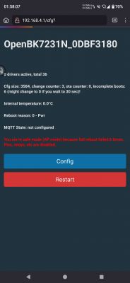
    OpenBK7231N user interface in safe mode with red error message.

    Many thanks,
    TL
  • ADVERTISEMENT
  • #2 21239492
    hartzell
    Level 7  
    Hi @tlpelektroda -- I can't help with your issue, I'm still trying to get my very first device flashed with OpenBK. I'm working with the same power strip that you are, have an older one that's running Tasmota happily and have been trying to get more, but everything's been turning up with the new chips.

    May I ask how you're flashing it?

    I have a pin jig that I use to flash the ESP devices and have been trying to get it to work (just give me the chip info) but it always just times out. I have TX<->RX and RX<->TX and 3.3V and ground, and after I've started ltchiptool I touch the pogo pin that's connected to CEN (tried both the one on the corner and the one that's 2 pins in) without any luck. I've tried the 3.3V from the UART board and from a simple breadboard power supply that I have, don't have anything fancier.

    Any recommendations or pictures or suggestions?

    Thanks!
  • #3 21239720
    tlpelektroda
    Level 2  
    >>21239492 Hi @hartzell -- I feel your pain! I tried to make a homemade Rube Goldberg jig with pogo pins and rubber bands and metal clips, but I could never get mine to work -- it never connected successfully to initialize the flash. How did you make your jig, do you have a 3D printer? I actually tried to see if anyone had made one for the CB3S chip but didn't see any; perhaps I should have just looked for a TYWE3S jig actually, as I read they're supposedly pin compatible. I too have several older versions of these power strips that I also happily run Tasmota on (until one of the Jinvoo ones started malfunctioning ... which is why I bought the new ones, that all seem to have the CB3S chip).

    Anyway so short answer is: I had to solder wire leads to the CB3S chip, to get it to work. And then the flashing worked pretty much on the first try, at least as I recall. You definitely have to do that CEN->GND thing, but with the command-line ltchiptool thing I used, it's pretty obvious when you have to touch them, a bit of trial and error but you get the hang of it (there's an initial long scroll of green lines as it polls the available IO ports, then it pauses, sometimes, then it prints this long blue text saying you have to touch the CEN->GND, and THEN when you do that it goes forward and starts the flashing progress 'bar'; but sometimes it skips either of those (lately/now, actually, it doesn't even require touching them at all somewhat disturbingly, the text scroll lines blow by and it goes right into flashing, seemingly successfully), sometimes doesn't work, or you do it too soon or too late etc.; but then you just start over, etc.. I only used the corner CEN pin, btw/fwiw, so can't say if that 2nd CEN pin also works.

    That's pretty much all I've got. Soldering works but it's a bit of hassle/gnarly, at least for me, because those chip pin contact points are so small and I'm not very good at soldering, apparently. I'm also trying my other solution, which I'm still trying different means of, of attaching those little 'clamp' or 'pincer' spring-loaded wire leads you can buy, instead of soldering. The chip pin/soldered points are so small though, my clamp/clips don't stay on them, they just snap off if I even breathe on them, never mind connecting all the FTDI leads and doing it. I just ordered 3 other kinds of those pincer/clamp leads to try today, so I'll definitely report back if I can get any of those working. I'm leaving the soldered power strip alone while awaiting if someone can hopefully help me understand why that now isn't working (the AP doesn't come up anymore), while I try getting the other two power strips, same model, working using the clamps, hopefully. And if you decide to solder yours and it still doesn't work, lmk, I might have forgotten some subtlety in how I got it working or something. If it does work for you, please lmk how the AP/OpenBK web interface works out! because that's where I'm stuck on my soldered strip.

    Thanks!
  • ADVERTISEMENT
  • #4 21239750
    divadiow
    Level 34  
    tlpelektroda wrote:
    I re-flashed the original Tuya factory firmware that it came with


    was this a full flash back starting 0x0, skip offset 0x0 and "all data" in the writing length box?

    are you able to capture the UART boot log after you exit safe mode and through the subsequent boot loops until it gets into safe mode again? maybe there are clues in that output about why it's crashing.
  • #5 21239773
    tlpelektroda
    Level 2  
    thanks for writing @divadiow! In response:

    divadiow wrote:
    was this a full flash back starting 0x0, skip offset 0x0 and "all data" in the writing length box?

    Apologies, but I have no idea! This is my first time trying OpenBeken, and I used the "ltchiptool" program (in a linux shell), passing no special parameters at all, for flashing both the OpenBK binaries and the Tuya binary I pulled from the device originally. For each I used the command: "ltchiptool flash write OpenBK7231N_QIO_1.17.728.bin", then "ltchiptool flash write read-result-file-1.bin [the arbitrary name I gave the pulled firmware]" to re-flash the Tuya factory firmware, then 'ltchiptool flash write OpenBK...' again to resume. I'm assuming the "writing length box" and other terms you mention refer to a GUI tool, either ltchiptool's (which I was not able to run because I am apparently missing some package dependency) or the OpenBeken "BK7231 GUI Flash Tool", which appears to only be available for Windows.

    divadiow wrote:

    are you able to capture the UART boot log after you exit safe mode and through the subsequent boot loops until it gets into safe mode again? maybe there are clues in that output about why it's crashing.

    Great idea and apologies again: how do I capture the UART boot log? The only output from ltchiptool is the stdout of what it's doing, described as the 'green/blue text' in my previous reply to @hartzell. Perhaps if I pass the "-r"/"--raw-log" flag to ltchiptool, which says it provides "Output logging messages with no additional styling" that might do it, but if not, is there another way to capture the UART boot log?  If there isn't I could try to get one of the GUIs running somehow.

    Many thanks,
    TL
  • Helpful post
    #6 21239793
    divadiow
    Level 34  
    OK. sure. I do not have any experience with their command-line tool but the GUI defaults are to write from 0x11000, skip offset 0x11000 and with a write length of 0x121000 if the file is QIO. No matter, perhaps we should just focus on the logs. OpenBeken is clearly to the point where it's booting and broadcasting.

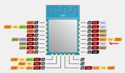
    On a CB3S module the logs can be captured by connecting RX on USB-TTL adaptor to the CB3S TX2 contact. Open COM port at 115200 baud with your terminal of choice.

    CB3S module pinout diagram.

    Also, at the stage where it's going into safe mode, is your CB3S powered by 3.3v only or is this happening when it's powered by the mains? Basically, how are you powering the CB3S?

    Added after 19 [minutes]:

    out of interest are the insides pretty much this still https://tasmota.github.io/docs/devices/SM-SO301/#flashing-and-configuration-pictures just with CB3S?
  • Helpful post
    #7 21240277
    hartzell
    Level 7  
    @tlpelektroda -- Yes, I 3D printed a jig that's actually for the TYWE3S, same spacing on the edges of the chip. This is the model: https://www.thingiverse.com/thing:4099748 and the pins he links to are still available on Amazon. It printed easily, though I needed to find some very small drill bits to clean out the holes before inserting the pins.

    Do you have access to a printer?

    Added after 2 [hours] 6 [minutes]:

    >>21239793 I have three of these newer models in my hands right now. They all look more or less like the TYWE3S picture you linked to, but they're slightly different circuitry surounding the module. One's a 16 (or 15, depending on which label you look at)A w/ a USB-C port, the others are all USB-A and 10A. Not surprising the USB-C is different, but kind of expected the other two to be the same thing.

    No luck reading any of them, perhaps because I haven't trield soldering wires yet.
  • #8 21240924
    tlpelektroda
    Level 2  
    Awesome @divadiow thank you for this!

    Ok I'm definitely going to try to monitor the UART logs, thanks for instructions how. More responses and dumb questions:

    divadiow wrote:
    On a CB3S module the logs can be captured by connecting RX on USB-TTL adaptor to the CB3S TX2 contact. Open COM port at 115200 baud with your terminal of choice.

    So, just checking/confirming, I should do this monitoring with the mains UNplugged right? I.e. poll the UART logs while the chip is running off the USB-TTL's 3.3v alone — after flashing is completed (presumably I can leave the RX/TX contacts between the CB3S and my USB-TTL and my computer as they were during the flashing?), but *before* trying to power up the 120v power strip itself, right? In fact, related dumb question — we *never* need to power up the strip, in order to flash OpenBeken, bring up its AP, and have the device join the network, etc... right? I believe that's right but can't remember how I did it with the previous Tasmota-flashed power strips I did this on, whether I had the mains power on at any phase during setup, or not.

    divadiow wrote:

    Also, at the stage where it's going into safe mode, is your CB3S powered by 3.3v only or is this happening when it's powered by the mains? Basically, how are you powering the CB3S?

    See previous response, but short answer is: yes, my CB3S is powered by the USB-TTL-supplied 3.3v only, during these tests (including the semi-successful ones, where the AP and web interface did come up but then never joined my network). Except maybe once or twice if/when I tried the whole test sequencing with the mains on.

    divadiow wrote:

    out of interest are the insides pretty much this still https://tasmota.github.io/docs/devices/SM-SO301/#flashing-and-configuration-pictures just with CB3S?

    Yes! Pretty much / AFAICT, same as the older models that I successfully flashed Tasmota onto. Notice though, I'm sure you did, that there is no GPIO-0 involvement on the CB3S, I think, like on the TYWE3S pinout, nor any CEN connections on the TYWE3S (nothing's connected to its RST or EN pins that match where the CENs are on the CB3S). Unless that's what the GPIO-0 is, essentially, on the TYWE3S chip or something.

    Added after 1 [minutes]:

    Nice / awesome @hartzell! No, I don't unfortunately have access to a printer AFAIK, but I do have an engineer friend who I think has one at his work. If his is not available, do you know if/where I could buy this jig from someone? If not I assume I could give these .FCStd and .stl files on the link you cited, to him, ya?

    hartzell wrote:
    @tlpelektroda -- Yes, I 3D printed a jig that's actually for the TYWE3S, same spacing on the edges of the chip. This is the model: https://www.thingiverse.com/thing:4099748 and the pins he links to are still available on Amazon. It printed easily, though I needed to find some very small drill bits to clean out the holes before inserting the pins.

    Do you have access to a printer?
  • Helpful post
    #9 21240989
    divadiow
    Level 34  
    tlpelektroda wrote:
    So, just checking/confirming, I should do this monitoring with the mains UNplugged right?

    100% UNplugged from the mains for anything flashing/logging. But wait, if you're powering the CB3S from USB-TTL alone then maybe it's not stable because of brownouts - the USB-TTL cannot provide enough current - this is usually the case. The general experience is that the 3.3v from a USB-TTL adaptor is often not good enough and an external 3.3v PSU should be used to be sure. Have you tried making the device safe again and then trying it on the mains alone or introducing an external 3.3v power source instead of relying on the USB-TTL?

    tlpelektroda wrote:
    In fact, related dumb question — we *never* need to power up the strip, in order to flash OpenBeken, bring up its AP, and have the device join the network, etc... right? I believe that's right but can't remember how I did it with the previous Tasmota-flashed power strips I did this on, whether I had the mains power on at any phase during setup, or not.


    Indeed, never use the mains for flashing or anything relating to the USB-TTL adaptor.

    Added after 2 [minutes]:

    divadiow wrote:
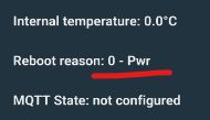
    USB-TTL alone then maybe it's not stable because of brownouts

    Screenshot of interface showing internal temperature 0.0°C, reboot reason (0 - Pwr), and MQTT state: not configured.
  • #10 21241010
    tlpelektroda
    Level 2  
    Interesting, wow thanks @divadiow, I'll definitely try that. My only pondering about this is, I think I've pretty much 'always' only used the 3.3v from a USB-TTL adaptor, I think, and never had this problem before. But if this fixes it, who am I to ponder?! I guess the first thing I have to figure out is how to get a powerful 'enough' 3.3v supply (I guess its 'amp rating' or something would be the measure?). Would the 3.7v LiPo batteries I have around do it? And if so, is it safe to connect 3.7v to a 3.3v supply pin on the CB3S chip? If not, my next try would be a 5 volt line from a typical USB charger plug/adapter, plugged into the wall, and then step it down to 3.3 with some kind of circuit board I think I also have lying around somewhere. Failing all that, would a 3.3v output pin from a Raspberry Pi work/do the trick, or even an Arduino board, do you think? That would be the easiest I think. I have a couple Pi's, the 'biggest' one is a Pi 4 Model B I think. Last question what did you mean "making the device safe again and then trying it on the mains alone" -- what's the making safe part, and then, on the mains alone, that means just plug it in, and when flashing I only connect the TX and RX lines from the USB-TTL to the chip? (and I guess then ground the CEN to the GND pin).

    Thanks so much again and sorry for the flurry of follow up dumb questions.

    divadiow wrote:
    tlpelektroda wrote:
    So, just checking/confirming, I should do this monitoring with the mains UNplugged right?

    100% UNplugged from the mains for anything flashing/logging. But wait, if you're powering the CB3S from USB-TTL alone then maybe it's not stable because of brownouts - the USB-TTL cannot provide enough current - this is usually the case. The general experience is that the 3.3v from a USB-TTL adaptor is often not good enough and an external 3.3v PSU should be used to be sure. Have you tried making the device safe again and then trying it on the mains alone or introducing an external 3.3v power source instead of relying on the USB-TTL?

    tlpelektroda wrote:
    In fact, related dumb question — we *never* need to power up the strip, in order to flash OpenBeken, bring up its AP, and have the device join the network, etc... right? I believe that's right but can't remember how I did it with the previous Tasmota-flashed power strips I did this on, whether I had the mains power on at any phase during setup, or not.


    Indeed, never use the mains for flashing or anything relating to the USB-TTL adaptor.

    Added after 2 [minutes]:

    divadiow wrote:
    USB-TTL alone then maybe it's not stable because of brownouts

    Screenshot of interface showing internal temperature 0.0°C, reboot reason (0 - Pwr), and MQTT state: not configured.
  • ADVERTISEMENT
  • #11 21241020
    divadiow
    Level 34  
    tlpelektroda wrote:
    "making the device safe again and then trying it on the mains alone" -- what's the making safe part, and then, on the mains alone, that means just plug it in, and when flashing I only connect the TX and RX lines from the USB-TTL to the chip? (and I guess then ground the CEN to the GND pin).


    as in, putting it back together and plugging it in to the mains as if it's completed - ie nothing to USB-TTL or any other power source. I was being cautious to recommend safe steps so I can't be seen to suggest anything that might get you electrocuted ;)

    The device will have its own LDO to provide the module with a stable 3.3v, so if the module is still rebooting when powered on mains you know the issue perhaps isn't power, then it's worth looking at the boot logs.
  • #12 21241053
    tlpelektroda
    Level 2  
    Oh sorry so you mean, put it back together more or less, plug it in, press the 'On' button on the strip (is that actually needed btw? or is the CB3S chip already energized on its own, i.e. 'unswitched'/always-on from the LDO, when you plug it in; I guess I'll find out), and then, see if the AP comes up on its own? In other words, don't actually try to *flash* another OpenBK binary with the mains on; you mean really, really have "nothing to the USB-TTL", including even the TX/RX lines.

    divadiow wrote:
    tlpelektroda wrote:
    "making the device safe again and then trying it on the mains alone" -- what's the making safe part, and then, on the mains alone, that means just plug it in, and when flashing I only connect the TX and RX lines from the USB-TTL to the chip? (and I guess then ground the CEN to the GND pin).


    as in, putting it back together and plugging it in to the mains as if it's completed - ie nothing to USB-TTL or any other power source. I was being cautious to recommend safe steps so I can't be seen to suggest anything that might get you electrocuted ;)

    The device will have its own LDO to provide the module with a stable 3.3v, so if the module is still rebooting when powered on mains you know the issue perhaps isn't power, then it's worth looking at the boot logs.
  • Helpful post
    #13 21241061
    divadiow
    Level 34  
    yes, on, powered as if you've just unboxed it. ie nothing connected to CB3S. You've flashed it to Openbeken already and now you just want to know if the USB-TTL 3.3v not providing the CB3S with enough power is the reason for the reboots.
  • ADVERTISEMENT
  • #14 21241080
    tlpelektroda
    Level 2  
    And not electrocute myself in the process. Got it, finally, lol. Will let you know how it goes, thanks again!

    divadiow wrote:
    yes, on, powered as if you've just unboxed it. ie nothing connected to CB3S. You've flashed it to OpenBeken already and now you just want to know if the USB-TTL 3.3v not providing the CB3S with enough power is the reason for the reboots.
  • Helpful post
    #15 21241407
    hartzell
    Level 7  
    >>21240924 @tlpektroda -- You should be able to get any of the online services to print one for you. I'm happy to send one your way, can probably get to it sometime in the next week. Send me a shipping address to tlpelektroda at alerce.com (temporary mailbox, fix the at-sign) and I'll send one your way.
  • #16 21241704
    tlpelektroda
    Level 2  
    That's so awesome and kind of you @hartzell thank you!! It shows how clueless I am about the 3D printing world though, I didn't even know that there were online services that did this. I'm happy to Venmo you whatever costs and time for your trouble for your generous offer to send me one, but why don't I see if there's a service close to me here in NYC that will do it so you don't have to. Do you have any recommendations of a good online site for me for NYC area delivery?

    hartzell wrote:
    >>21240924 @tlpektroda -- You should be able to get any of the online services to print one for you. I'm happy to send one your way, can probably get to it sometime in the next week. Send me a shipping address to tlpelektroda at alerce.com (temporary mailbox, fix the at-sign) and I'll send one your way.
  • Helpful post
    #17 21241715
    hartzell
    Level 7  
    >>21241704 The only company I've used before is Shapeways, and apparently they're out of business (wow, how things change). There are probably local delivery companies in NYC (there's _everything_ there, so...) but I think that your best bet would be an online company and have them ship it to you. Another alternative would be a local makerspace, someone there might help.

    I'm going to print a fresh one for myself (maybe it's not working for me because the pins have developed a wiggle), and am also going to do a jig for the KMC 30407 (fingers crossed), so it's not a burden.
  • #18 21241847
    tlpelektroda
    Level 2  
    >>21241715 Alright wow thanks, I'll definitely check around then now! I'll send my address to you anyway in case you have a moment and it's easy — I'll take even your dead one or discarded ones from your floor. They *can't be worse* than the DIY one I made, talk about wiggling, I was using four hands I didn't have and rubber bands and paper clips and tape with some old PCB headers I cut, and the pins. On the other hand I definitely made all-points contact with the CB3S pins at least briefly — the main problem was I currently have only the arrow-headed-type pogo pins, I need the ones with concave tips so they marry the protruding but small soldered CB3S pins. So I should start by ordering those. But I'll keep foraging and gathering and will of course gratefully take anything you can spare if it happens or not. Thanks so much!
  • #19 21242887
    tlpelektroda
    Level 2  
    So, alas, @divadiow, unfortunately it didn't work -- no AP shows up, even on just the mains. I tried pretty much every permutation: mains-only; then back to CB3S USB-TTL powered only; reflashing with the latest OpenBeken binary first on USB-TTL power, then flashing with the mains; reflashing Tuya factory firmware; then back to OpenBeken, etc. The only hint of it showing up on my network was that the MAC address of the CB3S chip did advertise itself at one point, the router saw it and tried to authenticate it, but then "deauthenticated due to inactivity," and the CB3S chip 'twas never heard from again.

    After these AP failures, then, I turned to trying to pick up the UART logs. That didn't work either, at least with the setup I have -- I tried various versions of booting it up (under USB-TTL power; and then under mains) with the TX/RX wires connected through the USB-TTL, into a linux laptop where I was running a serial monitor provided by an Arduino IDE. The monitor only seemed to spit out garbage characters, and not very many, and only occasionally. But I'm not sure I was doing it right, or if the monitor was set up right (I did it at 115200 baud, etc.). Maybe I should try to get the OpenBeken GUI or ltchiptool GUI working, if either of those have a built-in serial monitor?

    Btw, I do see now where the offset is set. When I flash OpenBeken the stdout output says this:
    "I: |-- Success! Chip info: BK7231N
    I: Writing 'OpenBK7231N_QIO_1.17.730.bin'
    I: |-- Start offset: 0x11000 (auto-detected)
    I: |-- Write length: 1.1 MiB (auto-detected)
    I: |-- Skipped data: 68 KiB (auto-detected)"

    Does this offset indicate anything bad that might be causing the AP to not come up?

    Otherwise I'm back to square one. No AP; I can't seem to see UART logs, though I can work on that if you have any tips; and no cigar in general for provisioning my power strip on the OpenBeken web interface where I had done it before, etc. Not sure what to try next, except to solder, or if I can get a jig, pushpin flash OpenBeken onto one of the other new strips I have, to see if maybe somehow I 'broke' the networking on this one, and maybe the others are ok, not sure.

    divadiow wrote:
    yes, on, powered as if you've just unboxed it. ie nothing connected to CB3S. You've flashed it to OpenBeken already and now you just want to know if the USB-TTL 3.3v not providing the CB3S with enough power is the reason for the reboots.
  • #20 21242916
    divadiow
    Level 34  
    tlpelektroda wrote:
    The monitor only seemed to spit out garbage characters


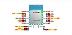
    Please confirm you're trying to get the UART logs from TX2, not TX1. 115200 baud is correct.

    Pin diagram of CB35 module with functional labels.

    tlpelektroda wrote:
    Does this offset indicate anything bad that might be causing the AP to not come up?


    No. The offset means it is just skipping the bootloader, which is included in QIO firmware.

    start address = where on your chip it'll start programming from
    skip offset (input file) = how much from the beginning of the file you're burning it'll not program - eg the bootloader, if offset is 0x11000 and it's a QIO file

    If you want to be sure your RF isn't broken and you want to get back to factory 100%, assuming you have a working backup, you can program your backup starting from 0x0, so:

    start address - 0x0
    skip offset - 0x0
    writing length - clear any values (all data written)

    then use Easy Flasher GUI to flash OBK as normal

    Added after 3 [minutes]:

    Easy Flasher does not include a serial terminal, but there are many around that should be fine - Putty, Realterm etc

    Added after 10 [minutes]:

    did you take a full flash backup before pairing it to Tuya app? If so, please feel free to post it. Or if there's a chance is contains credentials, and you want to, send it to me and I can flash it and sanitise for public posting.
  • #21 21242941
    tlpelektroda
    Level 2  
    Ah, thanks so much for all this educational info.

    So, first, on the UART logs, I totally missed that subtlety, that it should be from TX2. I was definitely doing it off TX1. So I'll try that for sure.

    As for the offset, thanks for explaining. It prompts me to wonder though, I wonder if I broke something when, out of desperation, I occasionally tried flashing the CCtr/UG binaries, e.g. "OpenBK7231N_UG_1.17.720.bin". Since, I gather, the CCtr/UG versions *don't* have a bootloader with them, perhaps I overwrote or broke something by doing that, such that the subsequent QIO firmware would thenceforth never again be flashed properly?

    Related, if I try to flash it back to factory to confirm whether the RF works or not, like you suggest, (1) might this be helpful to 'reset' the UG vs. QIO/offset situation I potentially created, and (2) the only way I can tell if the full networking RF works, with the factory firmware, is by fully provisioning it through the Smart Life app (I think that's the only way it gets assigned an IP and 'shows up' on my network). If so, will fully provisioning the factory firmware prevent me from flashing OBK forever after? (like I believe it did in the old Tuya-Convert days).

    divadiow wrote:
    tlpelektroda wrote:
    The monitor only seemed to spit out garbage characters


    Please confirm you're trying to get the UART logs from TX2, not TX1. 115200 baud is correct.

    Pin diagram of CB35 module with functional labels.

    tlpelektroda wrote:
    Does this offset indicate anything bad that might be causing the AP to not come up?


    No. The offset means it is just skipping the bootloader, which is included in QIO firmware.

    start address = where on your chip it'll start programming from
    skip offset (input file) = how much from the beginning of the file you're burning it'll not program - eg the bootloader, if offset is 0x11000 and it's a QIO file

    If you want to be sure your RF isn't broken and you want to get back to factory 100%, assuming you have a working backup, you can program your backup starting from 0x0, so:

    start address - 0x0
    skip offset - 0x0
    writing length - clear any values (all data written)

    then use Easy Flasher GUI to flash OBK as normal


    Added after 7 [minutes]:

    Hi, well, I never 'fully' paired it to the Tuya app -- after reflashing with the factory firmware, I just got the strip into 'fast-blink' AP mode, or whatever it's called, and then tried to look for and add it in the Tuya app, but then I backed off and cancelled because I was afraid Tuya might then permanently own it.

    So given that, which backup should I post or send to you? I have the factory Tuya firmware that I backed up before first trying to flash OpenBK. Then I have one or two backups of 'successful' OpenBK flashes, though mileage varies there because I tried so many versions, not sure which one reflected the times where the AP and web page did come up.

    divadiow wrote:

    did you take a full flash backup before pairing it to Tuya app? If so, please feel free to post it. Or if there's a chance it contains credentials, and you want to, send it to me and I can flash it and sanitize for public posting.
  • #22 21242960
    divadiow
    Level 34  
    tlpelektroda wrote:
    perhaps I overwrote or broke something by doing that, such that the subsequent QIO firmware would thenceforth never again be flashed properly?


    quite possibly. I think a total reflash to factory to wipe the slate clean is a good idea. This would wipe out anything you've done before with UG/QIO to whatever addresses.

    tlpelektroda wrote:
    the only way I can tell if the full networking RF works, with the factory firmware, is by fulling provisioning it through the Smart Life app (I think that's the only way it gets assigned an IP and 'shows up' on my network)

    If you are happy to do that, then I guess this would certainly prove all is well with hardware and the issue is something wrong with the software on the chip

    tlpelektroda wrote:
    will fully provisioning the factory firmware prevent me from flashing OBK forever after? (like I believe it did in the old Tuya-Convert days).


    no. not at all.

    Added after 3 [minutes]:

    tlpelektroda wrote:
    I have the factory Tuya firmware that I backed up before first trying to flash OpenBK

    this one. either to me, or on here if it was backed up before any pairing. There are many threads here with backups of factory firmware. Useful to other users sometimes if they need to flash back to factory for whatever reason.
  • #23 21242986
    tlpelektroda
    Level 2  
    Okidoke, here you go, attached is a binary of the factory firmware I pulled before first flashing OpenBK. Thanks so much for all your help and for taking a gander at this.

    divadiow wrote:

    tlpelektroda wrote:
    I have the factory Tuya firmware that I backed up before first trying to flash OpenBK

    this one. either to me, or on here if it was backed up before any pairing. There are many threads here with backups of factory firmware. Useful to other users sometimes if they need to flash back to factory for whatever reason.
  • #24 21242993
    divadiow
    Level 34  
    divadiow wrote:
    tlpelektroda wrote:
    is by fulling provisioning it through the Smart Life app (I think that's the only way it gets assigned an IP and 'shows up' on my network)

    but a step before that would be to assume everything is fine and just flash factory from 0x0 as described above, then go straight to OpenBeken

    Added after 31 [seconds]:

    tlpelektroda wrote:
    attached is a binary of the factory firmware I pulled before first flashing OpenBK

    thanks. cool.
  • #25 21243018
    tlpelektroda
    Level 2  
    Ok sounds good, and when I "then go straight to OpenBeken", should I flash that starting at 0x0 too, or to what ltchiptool defaults to/detects? (which appears consistently, as far as I've noticed, to be: "offset: 0x11000 (auto-detected)")

    divadiow wrote:

    but a step before that would be to assume everything is fine and just flash factory from 0x0 as described above, then go straight to OpenBeken
  • #26 21243031
    divadiow
    Level 34  
    tlpelektroda wrote:
    should I flash that starting at 0x0 too, or to what ltchiptool defaults to/detects?


    both LT and Easy Flasher will default to 0x11000 if flashing a QIO, it just may be less obvious in Easy Flasher. To be clear, flashing the QIO OpenBeken binary with Easy Flasher will be all that's needed or LT with the default 0x11000 start, 0x11000 file offset and 0x121000 length, after restoring to factory firmware.
  • #27 21243152
    tlpelektroda
    Level 2  
    OK, this is interesting and a bit bizarre. I reflashed as suggested the factory firmware at 0x0, then OpenBK with LT defaults, which were offset 0x11000 etc.. And nothing happened, it failed, no AP came up. So I was just about to report back that it didn't work, and in the meantime was simultaneously kind of fiddling with different combinations -- I brought it up on the mains, brought it up on USB-TTL power only, pressed the power button, shorted out the CEN->GND a couple of times, etc. And then suddenly, can't pinpoint exactly when, I glanced at my phone and saw the AP came up! So I quickly scrambled to punch in 192.168.4.1, and it started to bring up the web interface/page. And then the browser stalled/hung, didn't complete, and so I looked back at the current wifi network, and the AP was gone (which is why the browser page never finished loading). So I fiddled again, maybe shorted out the CEN->GND again, or something .... nothing worked .... and then, at some point, lo and behold, it was back. So once again I rushed to load the same page, this time it fully loaded, and I quickly punched through to the wifi config page, and retyped in my local LAN AP and password, and hit 'Submit' button. Right then, the browser said "Connection reset" or something. I thought, fine, it's now connecting to my network. But it didn't, and everything was gone again. No AP, no presence on the local LAN, nothing from the router that showed any presence of it, not even a trace of the MAC address again, at all. So I tried to reproduce the whole sequence again, restarting on the mains, restarting on USB-TTL power alone, shorting out CEN->GND on both, etc.. Nothing worked. It appears to be gone again.

    I have to go away and do something else for the next couple of hours, but what do you think of all this? (I can't try UART logs at the moment because I'm going to have to solder on another wire to TX2, which will take some set-up etc.).

    Here fwiw is the relevant output from the initial flashing of first the factory firmware and then OpenBeken, and then a snapshot I managed to get of web page before it was gone the first time I think:

    Factory:
    "I: Connecting to 'Beken 7231N' on /dev/ttyUSB0 @ 115200
    I: |-- Success! Chip info: BK7231N
    I: Writing 'read-result-file-1.bin'
    I: |-- Start offset: 0x0
    I: |-- Write length: 2 MiB (auto-detected)
    I: |-- Skipped data: 0 B"

    Then, directly/immediately, OpenBeken:
    "I: Detected file type: Beken QIO Firmware
    I: Connecting to 'Beken 72xx' on /dev/ttyUSB0 @ 115200
    I: |-- Success! Chip info: BK7231N
    I: Writing 'OpenBK7231N_QIO_1.17.730.bin'
    I: |-- Start offset: 0x11000 (auto-detected)
    I: |-- Write length: 1.1 MiB (auto-detected)
    I: |-- Skipped data: 68 KiB (auto-detected)"

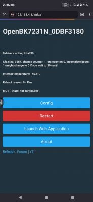
    Notice how this time, on the web page, there is no error about safe mode or anything, at least( :-D !). But does indicate "1" "incomplete boots", as well as an "Internal temperature" that I believe has never been reached in this part of the country at least, not sure what that's about lol, but anyway:
    OpenBK7231N interface screen with system information.

    divadiow wrote:
    tlpelektroda wrote:
    should I flash that starting at 0x0 too, or to what ltchiptool defaults to/detects?


    both LT and Easy Flasher will default to 0x11000 if flashing a QIO, it just may be less obvious in Easy Flasher. To be clear, flashing the QIO OpenBeken binary with Easy Flasher will be all that's needed or LT with the default 0x11000 start, 0x11000 file offset and 0x121000 length, after restoring to factory firmware.
  • #28 21243184
    divadiow
    Level 34  
    tlpelektroda wrote:
    but what do you think of all this?

    not too sure what to suggest next really. I'd hope there would be some clue in the TX2 logs.

    There's always trying factory fw with Tuya app I guess to be sure it works when in that state.

    Also, you could flash a factory firmware from any other BK7231N device (there are loads posted around) and then do OBK again. That would rule out a dodgy backup, but the file you posted does seem OK on initial dissection. I can flash it to dev board later today to just see if it boots and will let me convert it to OBK.

    Added after 9 [hours] 34 [minutes]:

    well I flashed I flashed a CB3S to your backup and it booted and was pairable in the Tuya app

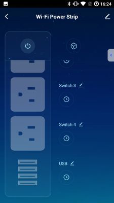
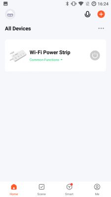
    User interface of an app managing a Wi-Fi power strip showing outlets and switches. Mobile app with All Devices section featuring a Wi-Fi power strip.
    and then to OBK
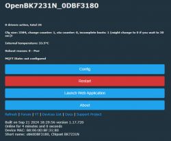
    Screenshot of the OpenBK7231N interface showing device information.
    factory boot log

    Code: Text
    Log in, to see the code
  • #29 21244297
    tlpelektroda
    Level 2  
    Hi, interesting, so may I ask, when it shows up as 'pairable' in the Tuya app, are you able to *actually pair* and provision it, i.e. go all the way through so it's fully set up on the Tuya app?

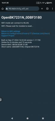
    Reason I ask is because now I've been able to flash OpenBk and bring up the AP/web interface deterministically. So I go through the motions, configure an IP (tried both static and DHCP), configure the wifi AP and password, and then hit submit, after which the transitional page says "WIFI: Please wait for module to reset..." (screenshot below). And then, once again, nothing happens after that. The OpenBK AP disappears, which is expected, but then the newly configured system never shows up on my LAN, no authentication attempts, no MAC broadcasts, nothing. The only slight subtlety maybe is that somewhere on the OpenBK web interface it says you have to 'reboot' the chip, or something, for settings to take effect. When I've submitted configurations, the 'uptime' clock keeps ticking, and it shows something like '6 minutes' uptime, i.e. it never rebooted. So one time I tried manually restarting it, in the hopes that would make the settings 'take', but it didn't make any difference. Is there anything there I should look at? (to confirm that the wifi/IP settings really 'take').

    OpenBK interface with a message about connecting to WLAN and a request for module reset.

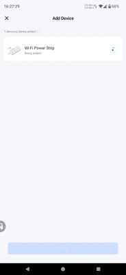
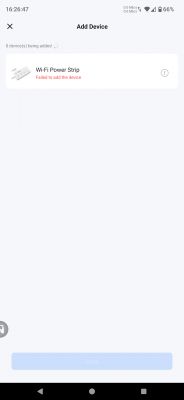
    So, I started over by reflashing the factory firmware back on, repowering it up, and then apparently all good -- I go into the Tuya app to add the wifi power strip manually etc. That's when, it turns out, it never works at all. After a several tries, I'm never able to successfully add it as a device. During the 'fast-blink' add, it finds the device, starts to add it, but then fails with the attached screenshot(s) below. One time, when I rebooted the strip and tried to add it again, the 'slow-blink' came up instead, but it never added the Tuya AP. So I reboot (although the strip sometimes reboots itself, not in a good looking way, during the add process) to bring up fast-blink again, try to add again etc. It never works. Often times, the fast-flashing blue LED just stops flashing midway through the add process. I believe that might be normal. But regardless of whether it stops blinking or continues blinking all the way through the end of the add process, it never succeeds and always fails. (The Tuya app 'add device clock' counts down from something like 3 minutes, and it always gets to the end, with failure).

    Tuya app screen while adding a Wi-Fi Power Strip device.
    Screenshot of an app showing a failed attempt to add a Wi-Fi device.

    So all of this seems to point to the fact that there may be something wrong with the hardware on my particular device, would you agree? It seems that would be confirmed if you're able to bring up the same factory firmware of mine on a different hardware or virtual test harness environment, and add it the Tuya app successfully.

    If it is hardware, not sure if it's worth trying to get the UART logs and figure out why, unless there's something that can be changed in the hardware or on the chip?

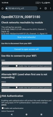
    One last hail-mary shot/guess, one small thing I noticed is that when I had the OpenBK web page 'Scan for local networks!,' instead of manually adding my local LAN wifi network AP, it only shows *2* 2.4Ghz networks, 2 out of 2, neither of which are the right ones, screenshot below. Plus, a wifi scan from any other device I have shows something like 20-30 networks available, near me and the device, not just the 2 (only) that the OpenBK shows. Could that be significant, in that the CB3S chip is somehow not 'receiving' well enough to be able to see my network/router (which is only about 10 feet away and visible to every other device)?  So perhaps an antenna problem, or something?

    Screenshot of the WiFi configuration interface for OpenBK7231N device.

    divadiow wrote:

    well I flashed I flashed a CB3S to your backup and it booted and was pairable in the Tuya app


    Added after 2 [hours] 17 [minutes]:

    tlpelektroda wrote:
    One last hail-mary shot .... So perhaps an antenna problem, or something?


    Eureka! so it turns out that was it. I repeated the whole sequence, but this time bringing it up with it sitting right next to my router. This time 'Scan local networks' showed my LAN AP right away. Connected, all good now. ... Or so it *seemed*...

    One thing I noticed right away is that, when I scanned for networks, this time right next to my router, once again, the OpenBK web page showed only *2* networks, one of which was mine and correct, but not any of the other 20-30 networks that are available to any other devices that do a wifi scan for APs.

    As soon as I moved the now-OBK-configured and provisioned power strip away from the router, it disappears. The power strip can't connect to my wifi network, even when it's only as far as 5 feet away from the router.

    So it would seem there's something wrong with the CB3S antenna?

    Or could it be something else? I see from CB3S diagrams that the antenna is baked into the PCB at the top of the chip. And it looks fine on the chip in this power strip AFAICT.

    Any idea whether there's any circuitry or section of the software/firmware on the chip, that would affect the receptivity, other than the characteristics of the physical antenna itself?

    Or perhaps that there's something wrong in OpenBeken, such that it only looks for and can connect to the 'top 2' highest-signal-strength networks it sees, and ignores all the others?

    Because otherwise this device is useless as-is. Of course I can now turn to the other new identical power strips I ordered, flash them and see if they suffer from the same poor receptivity, though.

    One last question in the meantime, if you or anyone might know -- is there a *template* around to configure the SM-SO301U pin/GPIO layout in OpenBeken?

    If there isn't, could I just use the same template that Tasmota, and I, used to configure the previous version of these strips, that had the TYWE3S chip? (considering that I think I read that they're pin-compatible?).
  • #30 21244352
    hartzell
    Level 7  
    >>21244297 Is your older power strip flashed with Tasmota? If so, you could bring it near the AP and see what the signal strength is, then move it away a bit and check, and a bit further, and ...

    Not sure what it'll tell us, but it might be informative.

Topic summary

The discussion revolves around the challenges faced while flashing OpenBeken firmware onto the SM-SO301-U power strip, which utilizes the CB3S (BK7231N) chip. The user successfully accessed the OpenBeken web interface but encountered persistent issues with the device not appearing on the local LAN despite multiple attempts to configure Wi-Fi settings. Various troubleshooting steps were suggested, including capturing UART logs, ensuring proper power supply, and using a jig for flashing. Users shared experiences with different flashing methods, including using ltchiptool and Easy Flasher, and discussed the importance of using stable power sources during the flashing process. The conversation also touched on the potential need for a factory reset and the possibility of hardware issues affecting the device's performance.
Summary generated by the language model.
ADVERTISEMENT