Hello everyone,
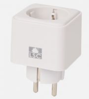
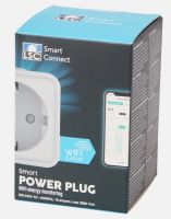
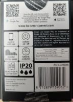
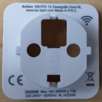
I am making this post because I made a guide on how to flash WB2S tuya board with BK7231T MCU from the new Action SmartPlug.
# Introduction
This guide provides instructions for flashing the Action LSC Smart Power Monitoring Plug with the WB2S Tuya board, featuring the [BK7231T MCU](https://developer.tuya.com/en/docs/iot/wb2s-module-datasheet?id=K9ghecl7kc479).
find the readme here : https://github.com/FlorianSoler/OpenBeken-Act...lsc-smartplug-with-monitoring-guide/tree/main
## Requirements:
* USB to TTL or UART reader
* Soldering iron
* Dupont cable or any wire for soldering
* [OpenBeken flasher software](https://openbekeniot.github.io/webapp/devicesList.html) or any other tool for flashing firmware.
# Step One
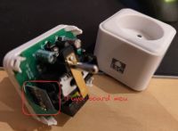
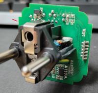
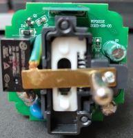
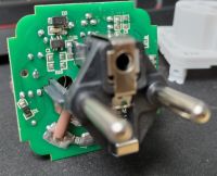
Begin by opening the smart plug case with a flat screwdriver.
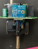
After opening, you should have access to the board.
# Step Two
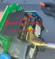
Locate the Tuya board number on the back of the blue board:
Google the board name, find Tuya documentation, and confirm the MCU (in this case, the board is a WB2S with [BK7231T MCU](https://developer.tuya.com/en/docs/iot/wb2s-module-datasheet?id=K9ghecl7kc479)). The manufacturer provides all the required data for flashing:
| Pin No. | Symbol | I/O type | Function |
|---------|--------|----------|--------------------------------------------------------|
| 1 | VBAT | P | Power supply pin (3.3 V), connected to VBAT on IC |
| 2 | PWM2 | I/O | Common GPIO, connected to P8 on IC |
| 3 | GND | P | Power supply reference ground pin |
| 4 | PWM1 | I/O | Common GPIO, connected to P7 on IC |
| 5 | 1RX | I/O | UART1_RXD, used as user-side serial interface, connected to P10 on IC |
| 6 | PWM0 | I/O | Common GPIO, connected to P6 on IC |
| 7 | 1TX | I/O | UART1_TXD, used as user-side serial interface, connected to P11 on IC |
| 8 | AD | AI | ADC pin, connected to P23 on IC |
| 9 | PWM4 | I/O | Common GPIO, connected to P24 on IC |
| 10 | CEN | I | Low-level reset, high-level active, Docking IC-CEN (internally pulled high) |
| 11 | PWM5 | I/O | Common GPIO, connected to P26 on IC |
# Step Three
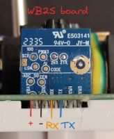
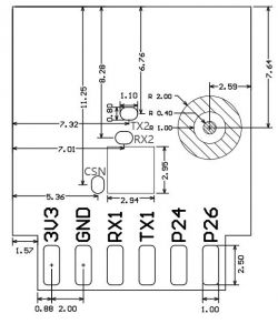
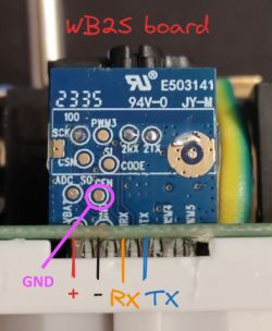
Solder wires on the GROUND, VBAT, RX, and TX pins. Highlighted pinout:
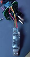
Connect pinout wires to the USB to UART adapter (ensure the MCU supports only 3.3V), and check Tuya RX is on the TTL board's TX and vice versa.
# Step Four
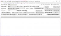
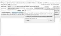
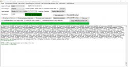
Plug the UART reader into your computer and launch [OpenBeken flasher software](https://openbekeniot.github.io/webapp/devicesList.html).
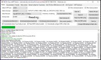
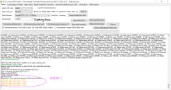
Start by making a firmware dump (backup) by clicking **Do firmware backup (read) only**.
After making the backup, obtain the firmware pinout configuration in JSON, and save it.
Locate the corresponding firmware and select the right one for your MCU, using the **_UA.bin** file, and click flash.
# Step Five
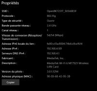
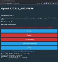
Unsolder all wires, put the board back in its enclosure, and plug it into an outlet. You should be able to see a WiFi hotspot:
Go to the WiFi properties, enter the gateway IP in a web browser:
# Step Six
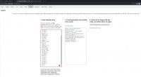
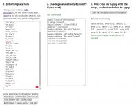
Configure the power plug by inserting the JSON obtained in Step Four. Go to **launch web app** and into **import**, paste the JSON, and click **clear OBK and apply new script**.
here my json obtained by reading the dump firmware :
# Congrat ! you have flash your action smart plug !
### Refer to [Tasmota Getting-Started](https://tasmota.github.io/docs/Getting-Started/#__tabbed_2_2) or [OpenBeken website](https://openbekeniot.github.io/webapp/devicesList.html) guide for connecting this to you wifi and for using **MQTT**.
I am making this post because I made a guide on how to flash WB2S tuya board with BK7231T MCU from the new Action SmartPlug.
# Introduction
This guide provides instructions for flashing the Action LSC Smart Power Monitoring Plug with the WB2S Tuya board, featuring the [BK7231T MCU](https://developer.tuya.com/en/docs/iot/wb2s-module-datasheet?id=K9ghecl7kc479).
find the readme here : https://github.com/FlorianSoler/OpenBeken-Act...lsc-smartplug-with-monitoring-guide/tree/main
## Requirements:
* USB to TTL or UART reader
* Soldering iron
* Dupont cable or any wire for soldering
* [OpenBeken flasher software](https://openbekeniot.github.io/webapp/devicesList.html) or any other tool for flashing firmware.
# Step One
Begin by opening the smart plug case with a flat screwdriver.
After opening, you should have access to the board.
# Step Two
Locate the Tuya board number on the back of the blue board:
Google the board name, find Tuya documentation, and confirm the MCU (in this case, the board is a WB2S with [BK7231T MCU](https://developer.tuya.com/en/docs/iot/wb2s-module-datasheet?id=K9ghecl7kc479)). The manufacturer provides all the required data for flashing:
| Pin No. | Symbol | I/O type | Function |
|---------|--------|----------|--------------------------------------------------------|
| 1 | VBAT | P | Power supply pin (3.3 V), connected to VBAT on IC |
| 2 | PWM2 | I/O | Common GPIO, connected to P8 on IC |
| 3 | GND | P | Power supply reference ground pin |
| 4 | PWM1 | I/O | Common GPIO, connected to P7 on IC |
| 5 | 1RX | I/O | UART1_RXD, used as user-side serial interface, connected to P10 on IC |
| 6 | PWM0 | I/O | Common GPIO, connected to P6 on IC |
| 7 | 1TX | I/O | UART1_TXD, used as user-side serial interface, connected to P11 on IC |
| 8 | AD | AI | ADC pin, connected to P23 on IC |
| 9 | PWM4 | I/O | Common GPIO, connected to P24 on IC |
| 10 | CEN | I | Low-level reset, high-level active, Docking IC-CEN (internally pulled high) |
| 11 | PWM5 | I/O | Common GPIO, connected to P26 on IC |
# Step Three
Solder wires on the GROUND, VBAT, RX, and TX pins. Highlighted pinout:
Connect pinout wires to the USB to UART adapter (ensure the MCU supports only 3.3V), and check Tuya RX is on the TTL board's TX and vice versa.
# Step Four
Plug the UART reader into your computer and launch [OpenBeken flasher software](https://openbekeniot.github.io/webapp/devicesList.html).
Start by making a firmware dump (backup) by clicking **Do firmware backup (read) only**.
After making the backup, obtain the firmware pinout configuration in JSON, and save it.
Locate the corresponding firmware and select the right one for your MCU, using the **_UA.bin** file, and click flash.
# Step Five
Unsolder all wires, put the board back in its enclosure, and plug it into an outlet. You should be able to see a WiFi hotspot:
Go to the WiFi properties, enter the gateway IP in a web browser:
# Step Six
Configure the power plug by inserting the JSON obtained in Step Four. Go to **launch web app** and into **import**, paste the JSON, and click **clear OBK and apply new script**.
here my json obtained by reading the dump firmware :
Code: JSON
# Congrat ! you have flash your action smart plug !
### Refer to [Tasmota Getting-Started](https://tasmota.github.io/docs/Getting-Started/#__tabbed_2_2) or [OpenBeken website](https://openbekeniot.github.io/webapp/devicesList.html) guide for connecting this to you wifi and for using **MQTT**.


