logo elektroda
logo elektroda
X
logo elektroda

How to upload OpenBeken to sockets with WB2S and BL0937? Flashing error

Mad_Maxs 1386 11
ADVERTISEMENT
Treść została przetłumaczona polish » english Zobacz oryginalną wersję tematu
  • #1 20950976
    Mad_Maxs
    Level 11  

    Hello, I have just received two WB2S sockets with BL0937, in which I am trying to install OpenBeneka, but without success.
    Screenshot showing an offer for the EWelink UE 20A smart Wi-Fi plug.
    https://pl.aliexpress.com/item/1005005979222799.html
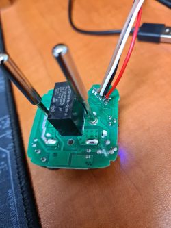
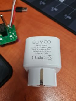
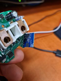
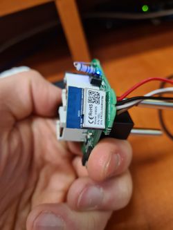
    Image of a circuit board with attached wires. Close-up view of an ELIVCO smart socket with technical specifications. The image shows a circuit board with electronic components, held in a hand. Close-up of an electronic module held in hand.
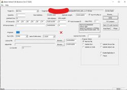
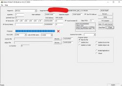
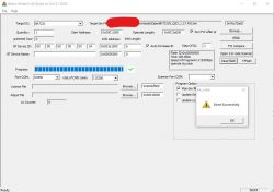
    When reading flash, everything goes fine, although it takes over 100 seconds. When trying to upload the current version of OpenBK7231N_QIO_1.17.453.bin it is already FAILED.
    Screenshot of Beken Writer V1.60 software used for firmware flashing. Screenshot of Beken Writer software for programming the BK7231 microcontroller. Screenshot of Beken Writer software during OpenBK7231N flashing attempt.

    What could be wrong?
  • ADVERTISEMENT
  • #2 20951029
    p.kaczmarek2
    Moderator Smart Home
    Using bkWriter 1.60 is not recommended. The new flasher does better, also being able to detect Tuya configuration automatically:
    https://github.com/openshwprojects/BK7231GUIFlashTool
    In addition, from the post, it seems that you are uploading the N version on the T platform (WB2S is BK7231T). This will not work.

    Use the correct flasher for the BK version you have (you have WB2S, so BK7231T), if it still won't move then solder WB2S and program off-chip.
    In this video we show you how to solder the chip:


    .
    Helpful post? Buy me a coffee.
  • ADVERTISEMENT
  • #3 20951233
    Mad_Maxs
    Level 11  
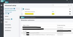
    Of course it works :) it's a pity that on startup, Eset Live Grid threw it out as a suspicious file when I tried to run it, because I was trying it on, but after that action I let it go :) no less, let loose outside the network on a separate laptop, it did the job.
    This socket of mine was not in the templates on the webapp, so below I give the pinout : "pins": {
    "6": "LED_n;1",
    "7": "BL0937CF;0",
    "8": "BL0937CF1;0",
    "10": "Btn;1",
    "24": "BL0937SEL;0",
    "26": "Rel;1"
    The socket has two LEDs, red and blue.
    With GPIO 6 set to LED, red indicates relay on, blue indicates relay off
    With GPIO 6 set to LED_n, both illuminate when the relay is on and neither when off

    I would prefer the blue one to indicate on and the red one to indicate off (or neither to light up), but I don't think this can be achieved since they are on the same pin
  • ADVERTISEMENT
  • #4 20951360
    p.kaczmarek2
    Moderator Smart Home
    I would ask for a full template, with the device name and links to the forum etc completed.

    The BK7231GUIFlashTool is compiled straight from Visual, but if you need to, you have the source here:
    https://github.com/openshwprojects/BK7231GUIFlashTool

    Very strange LED configuration, and what does it look like on the board, maybe there is a free GPIO to cut one of the paths and solder to a free pad, albeit on the back of the WB2S?
    Helpful post? Buy me a coffee.
  • ADVERTISEMENT
  • #5 20951394
    divadiow
    Level 35  
    >>20951233

    Screenshot shows advanced settings in Eset Endpoint Antivirus with the detection exclusions tab open.

    I had to add exclusions to Eset
  • #6 20951423
    Mad_Maxs
    Level 11  
    >>20951360
    Looking at the GPIO Finder, I see that driving the relay itself will turn off the red diode, so it would have to be cut off from the GPIO as the relay and driven separately, as you suggested.

    Added after 2 [hours] 8 [minutes]:


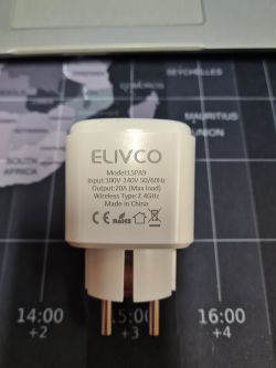
    View of an ELIVCO LSPA9 smart plug lying on a world map.

    Below is the template, without a photo because the sockets were left at work, I will complete it tomorrow :) There is already one in the template database, but it is from CB2S and the pinout is different than mine. If there`s anything else missing, let me know and I`ll fix it
    Code: JSON
    Log in, to see the code
  • #7 20952520
    divadiow
    Level 35  
    did you happen to take a factory fw backup?
  • #8 20953608
    Mad_Maxs
    Level 11  
    @divadiow probably yes, do you need it?
  • #9 20960837
    divadiow
    Level 35  
    was only curious. feel free to post it.
  • #10 21350498
    piteqpl
    Level 12  
    Allow me to refresh the subject a little. Well, I also encountered a difficult piece, and this already at the stage of reading. Apparently it reads the contents of the memory and writes them to the file, but it does not want to read the Tuya configuration and gives such an error:
    Quote:
    Loaded total 0x200000 bytes
    Wrote 2097152 to readResult_BK7231T_QIO_2024-03-12-58-22.bin
    Backup 2MB created, now will attempt to extract OBK config.
    It's not an OBK config, header is bad
    OBK config not found.
    Backup 2MB created, now will attempt to extract Tuya config.
    Tuya config extractor - magic is at 2023424
    Saving debug Tuya decryption data to lastRawDecryptedStrings.bin
    Failed to extract Tuya keys - no json start found
    Sorry, failed to extract keys from Tuya Config in backup binary.

    Model to:
    Quote:
    LSPA9BPv2.1DL
    .
    This is exactly what is written on the laminate of the board.
    What am I doing wrong that it won't read my configuration?
  • #11 21350506
    p.kaczmarek2
    Moderator Smart Home
    Post a copy of the 2MB batch, unless you paired with Tuya and are afraid to share your WiFi data....

    But still, it might not work sometimes, then you have other options:
    - test to the limit with templates of similar sockets:
    https://openbekeniot.github.io/webapp/devicesList.html
    - open the case and visually see what is connected where, a multimeter will also help
    - use the GPIO doctor and experimentally hit where the relay is and where the LED and button are:
    GPIODoctor in OpenBeken - a convenient way to learn about GPIO roles in an IoT device .

    But since you say you have the LSPA9 model then there's probably a WB2S or CB2S inside, it doesn't have a lot of pins so there's not a lot of potential combinations to test. And probably some template from the base will already fit anyway.
    Helpful post? Buy me a coffee.
  • #12 21350676
    piteqpl
    Level 12  
    Inside is a WB2S.The socket is even twinned with the one in the photos. Admittedly it was paired, but with a network that is only switched on for testing and experimentation purposes, so even if the password leaks it won't be much of a tragedy. Right now I'm away from home and have no way to make the dump available, but somewhere around 7pm I'll be happy to make it available. I'd just like to add that I tried to pull the configurations from the dump with BK7231Flasher, but it gives an error about no key or something similar.

    Edit1
    Ok.Attached the dump.

    Edit2
    Continuation of my battle: I opened the dump in hexeditor, searched for the words "pin" and here is the result:
    {sel_pin_pin:24,rl1_lv:1,bt1_pin:10,net_trig:2,jv:1.1.5,netled1_lv:0,bt1_type:0,nety_led:1,vi_pin:8,resistor:1,over_cur:16000,bt1_lv:0,reset_t:5,netled1_pin:6,chip_type:0,lose_vol:90,over_vol:265,module:WB2S,ele_pin:7,ch_cddpid1:9,ch1_stat:2,rl1_type:0,ch_num:1,rl1_pin:26,netn_led:0,vol_def:0,ch_dpid1:1,sel_pin_lv:1,crc:40,}         
    .

Topic summary

The discussion centers on difficulties flashing the OpenBeken firmware (OpenBK7231N_QIO_1.17.453.bin) onto WB2S smart sockets equipped with the BL0937 energy monitoring chip. While reading the flash memory succeeds, uploading the firmware fails with errors. The user shared images and links to the device and firmware attempts. Suggestions include adding antivirus exclusions (Eset) to prevent interference, verifying GPIO pin assignments using GPIO Finder and GPIODoctor tools, and creating or adjusting device templates for the ELIVCO LSPA9 WB2S with BL0937, which uses the BK7231T chip. A partial device template with pin mappings was provided, highlighting pins for LED, BL0937 signals, button, and relay. Backup of factory firmware dumps was discussed to aid in analysis, though extracting Tuya configuration keys proved problematic. Troubleshooting steps recommended include testing similar device templates, physically inspecting the board with a multimeter, and confirming correct pinouts due to limited pin availability on WB2S/CB2S boards. The user also examined the firmware dump in a hex editor to identify configuration parameters such as pin assignments and voltage thresholds. Overall, the challenge involves overcoming flashing errors and correctly mapping hardware interfaces to successfully deploy OpenBeken firmware on WB2S sockets with BL0937 metering.
Summary generated by the language model.
ADVERTISEMENT