logo elektroda
logo elektroda
X
logo elektroda

How to connect 4 BH1750 sensors to ESP32 with Tasmota? I2C configuration

Daro1003 291 4
ADVERTISEMENT
Treść została przetłumaczona polish » english Zobacz oryginalną wersję tematu
  • #1 21391605
    Daro1003
    Level 33  
    ESP 32 and 4 pieces of BH1750 sensors.
    Hello I would like to connect 4 pieces of BH1750 under one ESP32 on Tasmot how should this be done ?
    Should I set up 4 I2C buses on different GPIO ? And to each separately connect the individual BH1750 sensors ??
  • ADVERTISEMENT
  • Helpful post
    #2 21393697
    p.kaczmarek2
    Moderator Smart Home
    I would start with Tasmota's documentation, but it doesn't talk about many devices:
    https://tasmota.github.io/docs/BH1750/
    And if the documentation is silent, you should check Github:
    https://github.com/search?q=repo%3Aarendst%2FTasmota%20BH1750%20&type=code
    https://github.com/arendst/Tasmota/blob/ddcdc...ta/tasmota_xsns_sensor/xsns_10_bh1750.ino#L81
    From what I can see they detect BH1750 as follows:
    Code: C / C++
    Log in, to see the code
    .
    That is, two buses and two sensors on each....

    Addresses:
    Code: C / C++
    Log in, to see the code
    .
    With this knowledge I would start by trying to connect two BH1750s to one I2C, but so that each has a different address. .
    And as for the second I2C bus, do you have any SDA1 and SCL1 and SDA2 and SCL2 there separately? Because as far as I can see there must be two buses of 2 sensors each.


    Fragment of the instruction for configuring ADD pins for the BH1750 sensor. .


    EDIT: I've read it again and I don't like it:
    Code: C / C++
    Log in, to see the code
    .
    And the size in general of this board.... it looks like they have a hard limit of two sensors. But run the two to start with and we'll think, you can always change their code and compile your own version of Tasmota.
    Helpful post? Buy me a coffee.
  • ADVERTISEMENT
  • #3 21394321
    Daro1003
    Level 33  
    I've just caught up once before somewhere on the web with what you pasted about addresses but there was no time to connect.
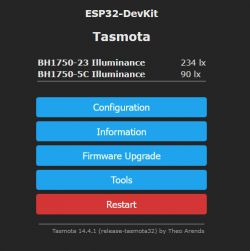
    So the result:

    Tasmota interface on ESP32-DevKit showing readings from two BH1750 sensors. .

    p.kaczmarek2 wrote:
    As for the second I2C bus, do you have any choices there for SDA1 and SCL1 and SDA2 and SCL2 separately? Because as far as I can see there must be two buses of 2 sensors each.
    .

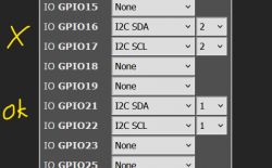
    I have just set it up like this:

    Fragment of the GPIO configuration interface with sensor settings. .

    Unfortunately it only sees two sensors on bus 1 GPIO 21 and 22 on the other bus it does not.


    PS Please drop a link to this spreadsheet:

    Instructions for configuring the I2C sensor address using the ADD pin. .

    I'm looking in the history but can't find it.
  • ADVERTISEMENT
  • #4 21394339
    p.kaczmarek2
    Moderator Smart Home
    This screenshot is from this page:
    https://randomnerdtutorials.com/arduino-bh1750-ambient-light-sensor/


    Well unfortunately the author of the code there did not foresee more than two sensors, you have to at least change this condition with two and here the size of the array:
    Code: C / C++
    Log in, to see the code
    .
    It is also worthwhile, instead of writing "2" from your finger, to enter some #define MAX_BH1750_SENSORS 4 .

    It is also possible that other places in the code may need to be changed, I haven't analysed this thoroughly.

    What do you need these four sensors for? Probably in the PlatformIO you would also run them quickly on the ESP....
    Helpful post? Buy me a coffee.
  • #5 21394489
    Daro1003
    Level 33  
    We are giving up on the subject of connecting 4 sensors to one ESP32 on the grounds that I can use 2 ESP32 units and connect two sensors to each.

    And now the best and funniest topic:

    p.kaczmarek2 wrote:
    And what do you need these four sensors for? Surely in a PlatformIO you would also run them quickly on the ESP...
    .

    I want to have four different controlled readings in numbers in Domoticz so that I can try to arrange the appropriate event in blockly.
    I thought that in order to have control I would use four light sensors and place each sensor in a separate cardboard box to have control over the light given and simulate the readings in domoticz.
    In this way I will test the operation of the stacked event in blockly.
ADVERTISEMENT