logo elektroda
logo elektroda
X

OBK PWMFrequency Command Issue on Pin 17, Frequency Stuck at 2kHz

omelchuk890 591 8
ADVERTISEMENT
  • #1 21688382
    omelchuk890
    Level 11  
    I needed to make WiFi control for a room heater.
    For this, I decided to use a ready-made WiFi relay module from Aliexpress, having slightly modified it.
    I planned to add a 18b20 sensor, and an output to a solid-state relay in slow PWM mode, 5-10s(0.2-0.1Hz).
    Let's leave the script out of the equation for now, and run into the main thing - the PWMFrequency command does not work at all - no matter what argument I set, 50, 100, 0.5, the PWM pin frequency remains 1.99998 kHz
    The duty cycle is adjusted by a slider via the web

    Maybe I'm doing something wrong?
    What is the range of PWM frequency adjustment?
    You can probably make a loop in the script and use variable delays to switch the pin, but this is somehow not Feng Shui :)
    Chipset: BL602
    pin 17 - PWM
    /autoexec.bat
    PWMFrequency 25
    If there are any difficulties, I will have to write everything again through the Arduino IDE on the ESP32C3 - but there will be no beautiful and convenient web...

    P.S. !!! The command works on the BK7231! But the minimum frequency is 1Hz...
  • ADVERTISEMENT
  • #2 21689148
    p.kaczmarek2
    Moderator Smart Home
    I don't remember now, but we have a limit for that in source code:
    Code: C / C++
    Log in, to see the code

    I can make PR with removed check so you can see if it works
    Helpful post? Buy me a coffee.
  • ADVERTISEMENT
  • ADVERTISEMENT
  • #4 21689166
    p.kaczmarek2
    Moderator Smart Home
    Maybe it could with different clk divider?
    Code: C / C++
    Log in, to see the code
    Helpful post? Buy me a coffee.
  • #5 21689211
    insmod
    Level 29  
    >>21689166
    Possible. And alternative is to use a different clk source. BL_PWM_CLK is defined to BL_PWM_XTAL_CLK which is defined to 40000000.
    If PWM_CLK_BCLK is to be used, BL_PWM_CLK would have to be 80000000. But that way minimum pwm frequency is likely to be 4000.
    Next is PWM_CLK_32K. BL_PWM_CLK is to be 32768? That way with 0 divider max frequency is 655hz? Minimum is 2hz?

    I think a script would be easier. Especially since frequency is a integer, not a float.
  • #6 21689346
    p.kaczmarek2
    Moderator Smart Home
    I can easily make a custom driver for that. Either with pin role (then maybe in obk core?), or configurable via autoexec.bat

    But maybe better a driver configurable in autoexec.bat

    Drive would use quick tick of OBK so it wouldn't have a great precision, but for lower frequencies it would be ok.

    How would setup look like? @omelchuk890 Specify pin, duty in % and frequency?
    Helpful post? Buy me a coffee.
  • ADVERTISEMENT
  • #7 21691981
    omelchuk890
    Level 11  
    >>21689346
    Now I use, as a test, the LED on the board - it is more visual.
    The frequency for the heater, or rather the PWM period, will be about 5 seconds.
    For this application, as a test, I plan to use the P regulator.
    This will be an additional module to a conventional heater, which in the absence of people will maintain the required minimum temperature, and before arrival remotely switch to the desired one. On the heater itself there is a regulator (native thermostat and thermal fuse), which will be set to maximum, so overheating does not threaten.
    I plan to implement it on 18B20 and SSR RM1A48D25.
    Another idea is to turn on and off the relay, 16A, when the SSR is off - for less sparking on the contacts.
    Now I tested such a script. There is a misunderstanding with the transitions, a feeling that in some places it works incorrectly. I have not added a sensor yet. The chip is now 7231N
    Powersave 1
    // chanel 5 this time power on pwm
    if $CH5==0 then setChannel 5 50
    // chanel 5 this time power off pwm
    setChannel 6 100
    // chanel 7- its koeff from second
    setChannel 7 50
    // chanel 6 this time power off pwm
    //if $CH6==0 then setChannel 5 0
    setChannelType 5 TextField
    // set label
    setChannelLabel 5 Turn_On_Time
    SetChannelVisible 2 0
    SetChannelPrivate 2 1
    
    mainLoop:
    
    if $CH1==1 then "goto pwmOn" else "goto pwmOff"
    
    // run pwm
    pwmOn:
    if $CH5>99 then backlog setChannel 5 100; setChannel 2 1; delay_s 1
    if $CH5<1 then backlog setChannel 5 0; setChannel 2 0; delay_s 1
    //if $CH5>100 then backlog setChannel 5 100; setChannel 2 1; delay_s 1;"goto mainLoop"  <- no run
    //if $CH5<0 then backlog setChannel 5 0; setChannel 2 0; delay_s 1;"goto mainLoop"  <- no run
    //if $CH5==0||$CH5==100 then "goto mainLoop"
    setChannel 6 100-$CH5
    setChannel 2 0
    delay_ms $CH6*$CH7
    if $CH5>0 then setChannel 2 $CH1
    delay_ms $CH5*$CH7
    goto mainLoop
    
    pwmOff:
    setChannel 2 0
    delay_s 1
    goto mainLoop

    It's still inexpensive here, $3 each, I bought new modules, maybe if I can flash them, I'll do it on them.
    OBK PWMFrequency Command Issue on Pin 17, Frequency Stuck at 2kHz
    OBK PWMFrequency Command Issue on Pin 17, Frequency Stuck at 2kHz
  • #9 21692095
    omelchuk890
    Level 11  
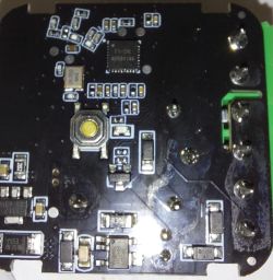
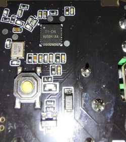
    The CHL at the end of the marking is confusing.
    If it is really 7238, then I think it is good, your team has implemented their support.
    Regarding the topic - I had to "hide" the channel, otherwise there is a constant sending of the status.
    Considering that the bit depth is not needed to be large, I think 100-200 is enough, and it is possible to implement this on timers.
    Primary check, for minimum/maximum - if true, then we do not start the counter, we simply set the output to the desired state.
    otherwise
    The counter is maximum, we start from low.
    A call, for example, every 40 ms, these are two periods of network voltage, counter check, decrement.
    if the desired value is reached, the output is in a high state, we count to 0, the procedure is reset.

    I don't use tasmota, esphome (there seems to be a slow PWM) and other stuff - only hardcore in the form of mqtt and node-red :) Also a voice assistant from Yandex via node, and Arduino IDE for peripherals
    And devices that thanks to you were flashed and linked to my zoo :)
    I really like your web!!!

Topic summary

A user attempted to implement WiFi control for a room heater using a modified WiFi relay module from Aliexpress with a BL602 chipset. The goal was to add an 18b20 temperature sensor and control a solid-state relay via slow PWM (0.1-0.2 Hz) on pin 17. However, the PWMFrequency command failed to change the PWM frequency, which remained fixed at approximately 2 kHz regardless of the input value (e.g., 0.5 Hz, 25 Hz, 50 Hz, 100 Hz). The duty cycle adjustment via a web slider worked, but frequency control did not. The user questioned the valid PWM frequency range for the BL602 and considered rewriting the control logic using Arduino IDE on an ESP32C3 for better web interface support. The issue highlights limitations or possible firmware/hardware constraints of the BL602 PWMFrequency command on pin 17.
Summary generated by the language model.
ADVERTISEMENT