Hi,
 .
.
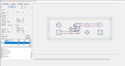
The project presented this time is purely programming but I hope it fits in this section and maybe someone will find it interesting or useful in the workshop. The aim of the project was to create a convenient-to-use GCode generator for making PCBs on a CNC milling machine. I design my PCBs in KiCAD so I focused on this input format. I've previously used FreeCAD for this purpose, but the conversion time and the number of operations required effectively discouraged me - processing one PCB could take me several hours, most of which was spent waiting for FreeCAD to convert everything.
As with previous projects, I decided to write the application in c# as a Windows Forms application using Visual Studio. The result is an application with which you can have a complete GCode generated in a few minutes.
Functions:
-Generation of code for milling paths including filled zones
-Generation of code for milling the shape of the insert, including any holes
-Code generation for hole drilling
-Possibility to select TOP or BOTTOM layer
-Automatic movement of the insert to 0.0 position
-Save settings
Description of operation :
The generation of the GCode takes place in several stages:
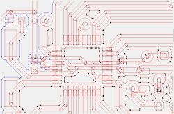
- The first stage takes place when the PCB file is opened. The file is parsed, all relevant elements of the PCB are searched for and saved as polygons consisting of segments and arcs. The filled zones are also converted to polygons. After this stage, the tile looks like this:
 .
.
At the same time, a list of all the holes is displayed in the console window, this is useful to select the correct drill bits. This is the point at which all milling and drilling parameters should be set. If we now leave the default option "ALL" and press "RUN", all the subsequent stages will be executed sequentially and at the end a window will be displayed in which we have to select where the generated code should be saved.
It is also possible to perform these steps one by one.
- The next step is to merge the polygons belonging to the paths. In order to optimise execution time, only segments belonging to the same network are merged. After this step, the board looks as follows:
 .
.
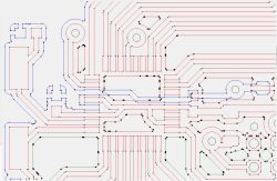
- In the next step, the paths are combined with the completed zones, also within the network:
 .
.
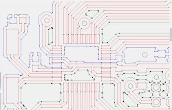
- The final step in preparation for milling is to merge the fragments of the filled zones which are connected by paths:
 .
.
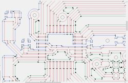
- All polygons are now ready so this stage generates milling paths at the correct distance from the prepared polygons, separately for milling the copper and separately for milling the plate shape.
 .
.
- The next step is to process the holes, matching them to the available drill list, the large holes are allocated for milling.
- The final step is the generation of the GCode from the prepared data.
What is missing:
Currently the milling of unfilled surfaces is not implemented - I did not need this for the time being.
The correctness of the insert is not checked, and the diameter of the cutter must be chosen so that it does not exceed the minimum distance between the paths.
The source code is available on github, feel free to test it and report comments and possible bugs.
https://github.com/r-gal/KiCAD2GCode
 .
.
The project presented this time is purely programming but I hope it fits in this section and maybe someone will find it interesting or useful in the workshop. The aim of the project was to create a convenient-to-use GCode generator for making PCBs on a CNC milling machine. I design my PCBs in KiCAD so I focused on this input format. I've previously used FreeCAD for this purpose, but the conversion time and the number of operations required effectively discouraged me - processing one PCB could take me several hours, most of which was spent waiting for FreeCAD to convert everything.
As with previous projects, I decided to write the application in c# as a Windows Forms application using Visual Studio. The result is an application with which you can have a complete GCode generated in a few minutes.
Functions:
-Generation of code for milling paths including filled zones
-Generation of code for milling the shape of the insert, including any holes
-Code generation for hole drilling
-Possibility to select TOP or BOTTOM layer
-Automatic movement of the insert to 0.0 position
-Save settings
Description of operation :
The generation of the GCode takes place in several stages:
- The first stage takes place when the PCB file is opened. The file is parsed, all relevant elements of the PCB are searched for and saved as polygons consisting of segments and arcs. The filled zones are also converted to polygons. After this stage, the tile looks like this:
 .
.
At the same time, a list of all the holes is displayed in the console window, this is useful to select the correct drill bits. This is the point at which all milling and drilling parameters should be set. If we now leave the default option "ALL" and press "RUN", all the subsequent stages will be executed sequentially and at the end a window will be displayed in which we have to select where the generated code should be saved.
It is also possible to perform these steps one by one.
- The next step is to merge the polygons belonging to the paths. In order to optimise execution time, only segments belonging to the same network are merged. After this step, the board looks as follows:
 .
.
- In the next step, the paths are combined with the completed zones, also within the network:
 .
.
- The final step in preparation for milling is to merge the fragments of the filled zones which are connected by paths:
 .
.
- All polygons are now ready so this stage generates milling paths at the correct distance from the prepared polygons, separately for milling the copper and separately for milling the plate shape.
 .
.
- The next step is to process the holes, matching them to the available drill list, the large holes are allocated for milling.
- The final step is the generation of the GCode from the prepared data.
What is missing:
Currently the milling of unfilled surfaces is not implemented - I did not need this for the time being.
The correctness of the insert is not checked, and the diameter of the cutter must be chosen so that it does not exceed the minimum distance between the paths.
The source code is available on github, feel free to test it and report comments and possible bugs.
https://github.com/r-gal/KiCAD2GCode
Cool? Ranking DIY


