Hi
I would like to present another project of mine, this time it is a CNC controller.
 .
.
 .
.
There are already a bunch of different types of CNC machine tool controllers on the market, but as usual I wanted to make something of my own.
Key design considerations:
- Location of all time-critical operations in the execution module.
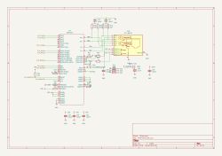
- Connection of the module with a PC using an Ethernet interface.
- Concurrent operation of 4 axes, expandable to 5.
- Possibility of future addition of encoder operation on axes.
- Inverter control with speed regulation.
- PC application running in Windows environment.
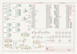
I decided to use the STM32H725 microcontroller - powerful, has lots of counters and at an affordable price.
As standard, I used FreeRTOS and the libraries I had already used in previous projects. The most important thing for me was to generate control pulses while maximising the use of hardware resources in order to achieve the greatest possible timing stability.
To do this, I used a serial connection of counters, the master is used to generate a variable frequency signal which corresponds to the travel speed, this signal then drives a set of counters - one for each axis, plus one for synchronisation.
In this way, I achieved an easy division between direction and speed of movement. This involves setting the ARR and PSC registers for each axis counter and the synchronising counter, respectively, for a given section of movement. The result is a specific number of pulses for each axis.
With the master counter, on the other hand, we can freely control the speed of travel of this section. By using the preload mode for the counters, we are able to load the parameters of the next section before the current section ends - we load the new values in the interval between the last pulse and the end of the section.
As a result, the episodes are executed without any timing disturbances.
The module receives simple commands from the PC, i.e. only segments and arcs, all already in machine coordinates. The arcs are then subdivided into short segments, and together with the straight segments are converted to register settings and buffered.
Each segment also has a pre-calculated start, end and maximum speed.
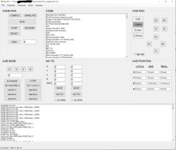
I decided to write the PC software in C# .net Windows Forms, in the Visual Studio environment. The choice was based on the simplicity of writing an extensive application with a GUI and, at the same time, not having to perform time-critical operations.
The main view of this application is to parse the G-Code and process it into simple commands sent to an external module.
The processing consists of several stages, the first one being the conversion of the G-Code from a string to an array of commands, at which stage the correctness of the syntax is checked, e.g. whether all commands are supported, variables defined and loops and conditional expressions properly closed.
The next stage is the processing of commands into a simple form - mathematical expressions are calculated, loops and subroutines are executed. At this stage, the maximum speed for each simple command (segments and arcs) is also calculated. The calculated fragments are placed in a fifo buffer.
The final stage is to scan the fifo buffer to calculate the allowed speed when passing between segments, taking into account the angle between the segments, the distance to the end of the buffer and the allowed accelerations. Once the start and end speeds have been calculated
the segments are already packed and sent to the control module.
The programme supports most of the standard G-Code expressions, and I have also added new G2.1 and G3.1 codes - these realise arcs in any plane parallel to the Z-axis - useful, for example, when milling decors.
The second additional functionality is the automatic measurement of surface irregularities - the specified area is probed and the measured grid of corrections is sent to the execution module. These corrections are then taken into account for all movements in this area. The function was developed for
The function was developed for the precise milling of PCBs, but can also be used for engraving.
The controller works stably, I have been using it for some time in my milling machine and am satisfied with it. Using the MONO library, the application also runs on Linux with limited functionality - only the 3D visualisation does not work.
What I would do differently:
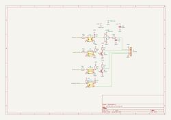
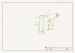
Basically probably just minor tweaks to the PCB, the circuit from the limiters could be improved and maybe consider completely hardware handling of the emergency stop and hard limit, bypassing the uC but that's mind blowing.
What else I would like to do:
First of all as I often write code by hand I would like to improve the code editor, add syntax highlighting, keyboard shortcuts etc. The second thing to improve is the 3D visualisation - so far it's quite clunky.
I'm also considering another approach, i.e. replacing my PC application with some sort of LinuxCNC plug-in, while for now I don't yet know if this is possible and how to go about it but maybe I'll look into it at some point.
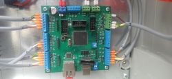
The program was created with a specific PCB in mind, but there's nothing to stop it running on other hardware, e.g. an EVM, as the PCB only has buffers and isolators on the inputs and outputs, so you can leave them out for experiments. You can also try to use another uC, it is important first of all that it has enough counters - 1 master + 1 slave 32bit + Number of axes x 1slave + 2 (speed control and HAL). It is also highly recommended that it has an FPU, as a large part of the calculations, especially speed and conversion of arcs into segments, is performed on float variables.
Code and PCB design in KiCAD format: https://github.com/r-gal/CNC
PC control program: https://github.com/r-gal/CNC_app
 .
.
 .
.
 .
.
 .
.
I would like to present another project of mine, this time it is a CNC controller.
 .
.
 .
.
There are already a bunch of different types of CNC machine tool controllers on the market, but as usual I wanted to make something of my own.
Key design considerations:
- Location of all time-critical operations in the execution module.
- Connection of the module with a PC using an Ethernet interface.
- Concurrent operation of 4 axes, expandable to 5.
- Possibility of future addition of encoder operation on axes.
- Inverter control with speed regulation.
- PC application running in Windows environment.
I decided to use the STM32H725 microcontroller - powerful, has lots of counters and at an affordable price.
As standard, I used FreeRTOS and the libraries I had already used in previous projects. The most important thing for me was to generate control pulses while maximising the use of hardware resources in order to achieve the greatest possible timing stability.
To do this, I used a serial connection of counters, the master is used to generate a variable frequency signal which corresponds to the travel speed, this signal then drives a set of counters - one for each axis, plus one for synchronisation.
In this way, I achieved an easy division between direction and speed of movement. This involves setting the ARR and PSC registers for each axis counter and the synchronising counter, respectively, for a given section of movement. The result is a specific number of pulses for each axis.
With the master counter, on the other hand, we can freely control the speed of travel of this section. By using the preload mode for the counters, we are able to load the parameters of the next section before the current section ends - we load the new values in the interval between the last pulse and the end of the section.
As a result, the episodes are executed without any timing disturbances.
The module receives simple commands from the PC, i.e. only segments and arcs, all already in machine coordinates. The arcs are then subdivided into short segments, and together with the straight segments are converted to register settings and buffered.
Each segment also has a pre-calculated start, end and maximum speed.
I decided to write the PC software in C# .net Windows Forms, in the Visual Studio environment. The choice was based on the simplicity of writing an extensive application with a GUI and, at the same time, not having to perform time-critical operations.
The main view of this application is to parse the G-Code and process it into simple commands sent to an external module.
The processing consists of several stages, the first one being the conversion of the G-Code from a string to an array of commands, at which stage the correctness of the syntax is checked, e.g. whether all commands are supported, variables defined and loops and conditional expressions properly closed.
The next stage is the processing of commands into a simple form - mathematical expressions are calculated, loops and subroutines are executed. At this stage, the maximum speed for each simple command (segments and arcs) is also calculated. The calculated fragments are placed in a fifo buffer.
The final stage is to scan the fifo buffer to calculate the allowed speed when passing between segments, taking into account the angle between the segments, the distance to the end of the buffer and the allowed accelerations. Once the start and end speeds have been calculated
the segments are already packed and sent to the control module.
The programme supports most of the standard G-Code expressions, and I have also added new G2.1 and G3.1 codes - these realise arcs in any plane parallel to the Z-axis - useful, for example, when milling decors.
The second additional functionality is the automatic measurement of surface irregularities - the specified area is probed and the measured grid of corrections is sent to the execution module. These corrections are then taken into account for all movements in this area. The function was developed for
The function was developed for the precise milling of PCBs, but can also be used for engraving.
The controller works stably, I have been using it for some time in my milling machine and am satisfied with it. Using the MONO library, the application also runs on Linux with limited functionality - only the 3D visualisation does not work.
What I would do differently:
Basically probably just minor tweaks to the PCB, the circuit from the limiters could be improved and maybe consider completely hardware handling of the emergency stop and hard limit, bypassing the uC but that's mind blowing.
What else I would like to do:
First of all as I often write code by hand I would like to improve the code editor, add syntax highlighting, keyboard shortcuts etc. The second thing to improve is the 3D visualisation - so far it's quite clunky.
I'm also considering another approach, i.e. replacing my PC application with some sort of LinuxCNC plug-in, while for now I don't yet know if this is possible and how to go about it but maybe I'll look into it at some point.
The program was created with a specific PCB in mind, but there's nothing to stop it running on other hardware, e.g. an EVM, as the PCB only has buffers and isolators on the inputs and outputs, so you can leave them out for experiments. You can also try to use another uC, it is important first of all that it has enough counters - 1 master + 1 slave 32bit + Number of axes x 1slave + 2 (speed control and HAL). It is also highly recommended that it has an FPU, as a large part of the calculations, especially speed and conversion of arcs into segments, is performed on float variables.
Code and PCB design in KiCAD format: https://github.com/r-gal/CNC
PC control program: https://github.com/r-gal/CNC_app
 .
.
 .
.
 .
.
 .
.
Cool? Ranking DIY


