Hi! This piece details building a two-wheeled self-balancing vehicle with a Raspberry Pi. It covers the rationale for choosing the Pi—repurposing idle hardware and learning Linux development via DIY work—lists components (Raspberry Pi, MPU6050, motor drivers, etc.), outlines development steps (sensor calibration, motor control, PID implementation), explains circuit/wiring logic with a focus on multi-threaded operations, dives into MPU6050 driver porting and attitude angle calculation for balance, and highlights key skills gained (Linux GPIO, I2C, PID tuning) and troubleshooting tips. A practical case for embedded Linux application.
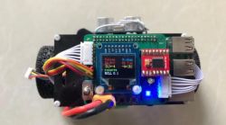
Why use a Raspberry Pi for a self-balancing scooter? The main reasons are as follows:
First, I couldn't bear to let it gather dust anymore;
Second, I want to learn Linux application development through DIY Raspberry Pi projects;
Third, I want to learn Linux driver development by working on DIY Raspberry Pi tasks;
Fourth, the Raspberry Pi offers high playability and scalability, which makes DIY Raspberry Pi projects more flexible and enjoyable;
Fifth, I want to gain firsthand experience of the differences between embedded Linux development and bare-metal development in the context of DIY Raspberry Pi and compare their advantages and disadvantages;
Sixth, I want to build something through DIY Raspberry Pi.
Based on the above reasons, I dusted off my long-forgotten Raspberry Pi and got started.
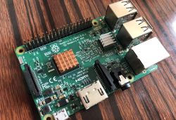
Materials list:
Raspberry Pi (models 3, 4, or Zero should all work);
MPU6050 sensor;
TB6612FNG or L298N motor driver (I've tried both, but recommend the former);
Motor, wheels, and chassis (available on Taobao for 130 yuan; the motor must include an encoder);
5V voltage regulator module (current rating preferably 2A or higher);
12V lithium-ion battery;
Breadboard (perforated board);
Header pins and sockets;
Wires, DuPont wires;
Soldering tools (soldering iron, solder, flux, etc.);
OLED display (optional);
Ultrasonic sensor (optional);
Custom-designed circuit board (optional, advantages include a clean and compact design with fewer connections, ensuring stability and reliability);
Other (optional, switches, buttons, mounting brackets, screws, power sockets, etc., depending on actual requirements);
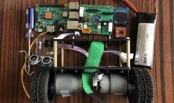
Program development steps:
1. Calibrate the MPU6050 sensor.
2. Control the motor
3. Obtain encoder signals and measure speed
4. Write PID control code
5. Calibrate the OLED display
6. Control the ultrasonic sensor
7. Set up Bluetooth
8. Adjust code logic and optimize code
Program code logic overview:
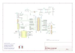
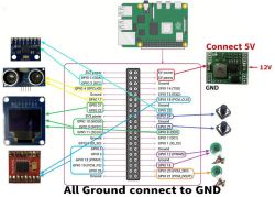
Circuit schematic diagram and wiring overview diagram:
The initialization process encompasses multiple threads and operations: there is a sensor reading, PID, and motor control thread that polls user - space GPIO interrupts, for the mpu6050 it drives the bus via I2C to read sensor data, for encoders it utilizes external interrupts to count interrupts and determine direction as well as read encoder devices, and implements PID control algorithms for position, speed, and steering loops while handling motor control with PWM speed control and direction control; an ultrasonic thread that works with wheel - related GPIO to trigger timing capture and calculate distance; an OLED thread that uses SPI to drive the bus and display content; a bluetooth communication thread for bluetooth configuration and reading from BLE devices; and a button handling task that polls user - space GPIO.
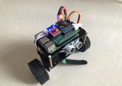
Final Effect:
Through the construction of a balance bike, the following knowledge points can be learned, mastered, or understood:
1. Linux GPIO control;
2. Linux I2C;
3. Linux SPI;
4. Linux interrupts;
5. Linux character device drivers;
6. Linux module development;
7. Linux Bluetooth control;
8. Linux threads;
9. Linux signals;
10. Linux system APIs, including open, read, write, lseek, ioctl, select, poll, usleep, sleep, gettimeofday, mmap, and others;
11. Implementation of digital PID;
12. PID control parameter tuning;
13. Filtering algorithms — Kalman filter, first-order complementary filter;
14. Makefile writing;
15. Methods for porting drivers;
16. Motor direction and speed (PWM) control methods;
17. Linux GDB debugging methods;
18. If designing your circuit board, schematic diagram, PCB layout, and PCB assembly.
The entire project is developed using the C language, so a good understanding of C is required. In my opinion, a self-balancing scooter is a reasonably comprehensive project with abundant resources and moderate difficulty, making it ideal for those who have learned various modules but are unsure about what small project to tackle next.
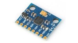
To make the small vehicle stand upright, we must first determine its attitude angle. Based on this angle, we can decide how the vehicle should move. This can be achieved using the MPU6050. The MPU6050 provides three-axis acceleration and three-axis angular velocity data. Through a special algorithm, we can calculate the three-axis angles. By knowing the angles, we can determine the vehicle's attitude relative to the ground and make corresponding control adjustments.
Currently, the most commonly used attitude estimation methods are the quaternion method, Kalman filtering, and complementary filtering. The specific algorithm principles are relatively complex and will not be covered in detail here. Those interested can refer to additional resources for further study. The MPU6050 provides a DMP library, which uses quaternions for the underlying algorithm. With this library, you only need to configure and port the driver to obtain the angles. Kalman filtering and complementary filtering both require calculating the MPU6050's raw data, which involves writing your algorithm code and presents a certain level of difficulty. However, many ready-made solutions are available, so even if you don't understand the details, you can use them, significantly reducing the difficulty.
Let's now take a look at the MPU6050 driver porting process.
The DMP driver consists of six files, including the firmware and API for the DMP algorithm. We do not need to concern ourselves with the specific implementation of these algorithms, functions, or APIs; we only need to understand how to use them. The official testing was done on the MSP430 platform, so when porting, we need to remove all MSP430-related header files and add the necessary header files for the new platform if required.
Open the inv_mpu.c file. At the beginning, you will see a section of comments that outlines all the tasks required for the porting process. Follow this order to complete the task.

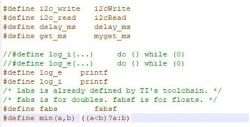
We need to define and implement the functions i2c_write, i2c_read, delay_ms, get_ms, reg_int_cb, labs, fabsf, and min. The other tasks in the DMP library call these interfaces. get_ms and reg_int_cb are used to obtain the timestamp and callback function, respectively. If they are not needed, they can be omitted. Labs is a function from the Linux standard library (stdlib.h). fabsf and fabs are functions from the math library (math.h), with the former taking a single-precision floating-point parameter and the latter taking a double-precision floating-point parameter. Here, we need a single-precision floating-point number. Their definitions are shown in the figure below:
Next, we need to implement the specific functions. Since we do not need a timestamp, we only need to implement i2cWrite, i2cRead, and delay_ms.
The parameter list for read/write functions is fixed, so the function prototype is also fixed. We cannot define it arbitrarily; otherwise, an error will be prompted during compilation. The parameter list consists of the slave address, register, data length, and data content. The address uses a 7-bit address mode.

Here, we first use the ioctl function to set the slave address, then call the I2C read/write function to read/write data. For more details about I2C on Raspberry Pi, please refer to my other article:
Linux Control of I2C/SMBus Devices
The millisecond delay function is implemented using the usleep function, which is a microsecond function that multiplies by 1000 to achieve a millisecond delay.

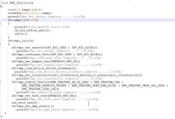
With the I2C read/write function and delay function, reading data from the MPU6050 is no longer an issue. The next step is to read the MPU6050's ID to ensure proper communication; configure the MPU6050, set its clock, and configure the acceleration and gyroscope ranges, etc. After that, call the DMP library's API to initialize the MPU and DMP, and read the DMP data to calculate the attitude angles.
void MPU6050_Init(void) {
MPU6050_setClockSource(MPU6050_CLOCK_PLL_YGYRO); // Set the clock
MPU6050_setFullScaleGyroRange(MPU6050_GYRO_FS_2000); // Gyroscope range setting
MPU6050_setFullScaleAccelRange(MPU6050_ACCEL_FS_2); // Accelerometer full-scale range ±2G
MPU6050_setSleepEnabled(0); // Enter working state, turn off sleep mode
MPU6050_setI2CMasterModeEnabled(0); // The AUX I2C of MPU6050, control MUX2, disable I2C master mode
MPU6050_setI2CBypassEnabled(1); // The I2C of the main controller, MPU6050's AUX I2C, enable bypass mode
DMP_Init();
}

ROLL represents roll angle, PITCH represents pitch angle, and YAW represents yaw angle. These are collectively referred to as Euler angles, defined in the context of aircraft.
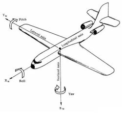
The vehicle can choose between ROLL or PITCH to maintain balance.
The specific code can be downloaded and studied from the driver.
Additionally, issues will inevitably arise during the porting process. Here are a few troubleshooting tips for reference:
1. Search online for error messages. Many errors have been encountered by others before, and searching for error messages will yield many similar issues, where solutions may be available.
2. Add logs. Insert log statements before and after the problematic code to print out data you believe may be causing the issue. Analyze the logs to identify the root cause.
3. Comment out irrelevant code. Remove code unrelated to the issue and test only the specific area in question. This allows you to focus on resolving a single issue without interference from other factors.
4. Use GDB. GDB is a powerful debugging tool that can significantly improve debugging efficiency if used effectively. It is recommended to learn how to use it, as it can achieve twice the result with half the effort.
Many errors are highly subtle and require immense patience to identify. Some error messages may be completely unrelated to the actual issue. It is crucial to look beyond the surface of the error to uncover its underlying cause.
Alright, that's all I have to say about porting the MPU6050. This is to give you an idea; the specifics will require hands-on practice.
Due to my limited expertise, there are inevitably omissions and errors in this article. It is intended to provide a general overview and outline of the process. I welcome everyone to join in the learning and discussion.

Why use a Raspberry Pi for a self-balancing scooter? The main reasons are as follows:
First, I couldn't bear to let it gather dust anymore;
Second, I want to learn Linux application development through DIY Raspberry Pi projects;
Third, I want to learn Linux driver development by working on DIY Raspberry Pi tasks;
Fourth, the Raspberry Pi offers high playability and scalability, which makes DIY Raspberry Pi projects more flexible and enjoyable;
Fifth, I want to gain firsthand experience of the differences between embedded Linux development and bare-metal development in the context of DIY Raspberry Pi and compare their advantages and disadvantages;
Sixth, I want to build something through DIY Raspberry Pi.
Based on the above reasons, I dusted off my long-forgotten Raspberry Pi and got started.

Materials list:
Raspberry Pi (models 3, 4, or Zero should all work);
MPU6050 sensor;
TB6612FNG or L298N motor driver (I've tried both, but recommend the former);
Motor, wheels, and chassis (available on Taobao for 130 yuan; the motor must include an encoder);
5V voltage regulator module (current rating preferably 2A or higher);
12V lithium-ion battery;
Breadboard (perforated board);
Header pins and sockets;
Wires, DuPont wires;
Soldering tools (soldering iron, solder, flux, etc.);
OLED display (optional);
Ultrasonic sensor (optional);
Custom-designed circuit board (optional, advantages include a clean and compact design with fewer connections, ensuring stability and reliability);
Other (optional, switches, buttons, mounting brackets, screws, power sockets, etc., depending on actual requirements);

Program development steps:
1. Calibrate the MPU6050 sensor.
2. Control the motor
3. Obtain encoder signals and measure speed
4. Write PID control code
5. Calibrate the OLED display
6. Control the ultrasonic sensor
7. Set up Bluetooth
8. Adjust code logic and optimize code
Program code logic overview:
Circuit schematic diagram and wiring overview diagram:
The initialization process encompasses multiple threads and operations: there is a sensor reading, PID, and motor control thread that polls user - space GPIO interrupts, for the mpu6050 it drives the bus via I2C to read sensor data, for encoders it utilizes external interrupts to count interrupts and determine direction as well as read encoder devices, and implements PID control algorithms for position, speed, and steering loops while handling motor control with PWM speed control and direction control; an ultrasonic thread that works with wheel - related GPIO to trigger timing capture and calculate distance; an OLED thread that uses SPI to drive the bus and display content; a bluetooth communication thread for bluetooth configuration and reading from BLE devices; and a button handling task that polls user - space GPIO.


Final Effect:

Through the construction of a balance bike, the following knowledge points can be learned, mastered, or understood:
1. Linux GPIO control;
2. Linux I2C;
3. Linux SPI;
4. Linux interrupts;
5. Linux character device drivers;
6. Linux module development;
7. Linux Bluetooth control;
8. Linux threads;
9. Linux signals;
10. Linux system APIs, including open, read, write, lseek, ioctl, select, poll, usleep, sleep, gettimeofday, mmap, and others;
11. Implementation of digital PID;
12. PID control parameter tuning;
13. Filtering algorithms — Kalman filter, first-order complementary filter;
14. Makefile writing;
15. Methods for porting drivers;
16. Motor direction and speed (PWM) control methods;
17. Linux GDB debugging methods;
18. If designing your circuit board, schematic diagram, PCB layout, and PCB assembly.
The entire project is developed using the C language, so a good understanding of C is required. In my opinion, a self-balancing scooter is a reasonably comprehensive project with abundant resources and moderate difficulty, making it ideal for those who have learned various modules but are unsure about what small project to tackle next.

To make the small vehicle stand upright, we must first determine its attitude angle. Based on this angle, we can decide how the vehicle should move. This can be achieved using the MPU6050. The MPU6050 provides three-axis acceleration and three-axis angular velocity data. Through a special algorithm, we can calculate the three-axis angles. By knowing the angles, we can determine the vehicle's attitude relative to the ground and make corresponding control adjustments.
Currently, the most commonly used attitude estimation methods are the quaternion method, Kalman filtering, and complementary filtering. The specific algorithm principles are relatively complex and will not be covered in detail here. Those interested can refer to additional resources for further study. The MPU6050 provides a DMP library, which uses quaternions for the underlying algorithm. With this library, you only need to configure and port the driver to obtain the angles. Kalman filtering and complementary filtering both require calculating the MPU6050's raw data, which involves writing your algorithm code and presents a certain level of difficulty. However, many ready-made solutions are available, so even if you don't understand the details, you can use them, significantly reducing the difficulty.
Let's now take a look at the MPU6050 driver porting process.
The DMP driver consists of six files, including the firmware and API for the DMP algorithm. We do not need to concern ourselves with the specific implementation of these algorithms, functions, or APIs; we only need to understand how to use them. The official testing was done on the MSP430 platform, so when porting, we need to remove all MSP430-related header files and add the necessary header files for the new platform if required.
Open the inv_mpu.c file. At the beginning, you will see a section of comments that outlines all the tasks required for the porting process. Follow this order to complete the task.

We need to define and implement the functions i2c_write, i2c_read, delay_ms, get_ms, reg_int_cb, labs, fabsf, and min. The other tasks in the DMP library call these interfaces. get_ms and reg_int_cb are used to obtain the timestamp and callback function, respectively. If they are not needed, they can be omitted. Labs is a function from the Linux standard library (stdlib.h). fabsf and fabs are functions from the math library (math.h), with the former taking a single-precision floating-point parameter and the latter taking a double-precision floating-point parameter. Here, we need a single-precision floating-point number. Their definitions are shown in the figure below:

Next, we need to implement the specific functions. Since we do not need a timestamp, we only need to implement i2cWrite, i2cRead, and delay_ms.
The parameter list for read/write functions is fixed, so the function prototype is also fixed. We cannot define it arbitrarily; otherwise, an error will be prompted during compilation. The parameter list consists of the slave address, register, data length, and data content. The address uses a 7-bit address mode.

Here, we first use the ioctl function to set the slave address, then call the I2C read/write function to read/write data. For more details about I2C on Raspberry Pi, please refer to my other article:
Linux Control of I2C/SMBus Devices
The millisecond delay function is implemented using the usleep function, which is a microsecond function that multiplies by 1000 to achieve a millisecond delay.

With the I2C read/write function and delay function, reading data from the MPU6050 is no longer an issue. The next step is to read the MPU6050's ID to ensure proper communication; configure the MPU6050, set its clock, and configure the acceleration and gyroscope ranges, etc. After that, call the DMP library's API to initialize the MPU and DMP, and read the DMP data to calculate the attitude angles.
void MPU6050_Init(void) {
MPU6050_setClockSource(MPU6050_CLOCK_PLL_YGYRO); // Set the clock
MPU6050_setFullScaleGyroRange(MPU6050_GYRO_FS_2000); // Gyroscope range setting
MPU6050_setFullScaleAccelRange(MPU6050_ACCEL_FS_2); // Accelerometer full-scale range ±2G
MPU6050_setSleepEnabled(0); // Enter working state, turn off sleep mode
MPU6050_setI2CMasterModeEnabled(0); // The AUX I2C of MPU6050, control MUX2, disable I2C master mode
MPU6050_setI2CBypassEnabled(1); // The I2C of the main controller, MPU6050's AUX I2C, enable bypass mode
DMP_Init();
}


ROLL represents roll angle, PITCH represents pitch angle, and YAW represents yaw angle. These are collectively referred to as Euler angles, defined in the context of aircraft.

The vehicle can choose between ROLL or PITCH to maintain balance.
The specific code can be downloaded and studied from the driver.
Additionally, issues will inevitably arise during the porting process. Here are a few troubleshooting tips for reference:
1. Search online for error messages. Many errors have been encountered by others before, and searching for error messages will yield many similar issues, where solutions may be available.
2. Add logs. Insert log statements before and after the problematic code to print out data you believe may be causing the issue. Analyze the logs to identify the root cause.
3. Comment out irrelevant code. Remove code unrelated to the issue and test only the specific area in question. This allows you to focus on resolving a single issue without interference from other factors.
4. Use GDB. GDB is a powerful debugging tool that can significantly improve debugging efficiency if used effectively. It is recommended to learn how to use it, as it can achieve twice the result with half the effort.
Many errors are highly subtle and require immense patience to identify. Some error messages may be completely unrelated to the actual issue. It is crucial to look beyond the surface of the error to uncover its underlying cause.
Alright, that's all I have to say about porting the MPU6050. This is to give you an idea; the specifics will require hands-on practice.
Due to my limited expertise, there are inevitably omissions and errors in this article. It is intended to provide a general overview and outline of the process. I welcome everyone to join in the learning and discussion.
Cool? Ranking DIY


