I'm attempting to replace the MCU on a smart plug with an ESP8266. I'd like to use the pin configuration for my existing 10 smart plugs, Kauf PLF10.
Here's the pinout for the Kauf plug for reference:
GPIO 0 – Red LED. The red LED will be lit when GPIO0 is output low, and off when GPIO0 is output high.
GPIO 2 – Blue LED. The blue LED will be lit when GPIO2 is output low, and off when GPIO2 is output high.
GPIO 4 – Relay output. When the GPIO4 output is high, the relay connects input power to output power. When GPIO4 is low, the relay opens and power is disconnected.
GPIO 5 – CF pin for power monitoring.
GPIO 12 – SEL pin for power monitoring.
GPIO 13 – Button input.
GPIO 14 – CF1 pin for power monitoring.
I know on the ESP8266, GPIO 2 and GPIO 0 are bootstrap pins, and should both be pulled up to boot normally.
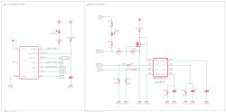
My issue is with the board - it seems that on the board, the GPIO for the Red LED goes through a resistor, then the LED, then another resistor, then connects back to the GPIO for the BL0937 SEL pin. I'm wondering why the Red LED wouldn't have its own circuit?
Ultimately, I'm trying to figure out if I connect the ESP8266 GPIO 0 to the cathode side of the red LED, will GPIO 0 be pulled down (and breaking normal boot)
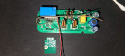
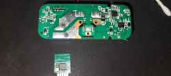
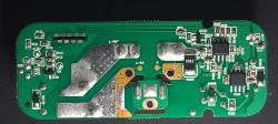
I've tried to be as faithful as possible creating the schematic using my multimeter and pictures of the board. I've attached an image of the schematic, as well as the GIMP image including all the image layers for inspection.

AI: Could you provide either the schematic you created or a clear textual description of the exact connections and components (including how the red LED, resistors, and SEL pin are interconnected)?
Image of schematic attached.
AI: What are the values of the resistors in the circuit path between GPIO 0, the red LED, and the SEL pin?
both resistors are 1k
Here's the pinout for the Kauf plug for reference:
GPIO 0 – Red LED. The red LED will be lit when GPIO0 is output low, and off when GPIO0 is output high.
GPIO 2 – Blue LED. The blue LED will be lit when GPIO2 is output low, and off when GPIO2 is output high.
GPIO 4 – Relay output. When the GPIO4 output is high, the relay connects input power to output power. When GPIO4 is low, the relay opens and power is disconnected.
GPIO 5 – CF pin for power monitoring.
GPIO 12 – SEL pin for power monitoring.
GPIO 13 – Button input.
GPIO 14 – CF1 pin for power monitoring.
I know on the ESP8266, GPIO 2 and GPIO 0 are bootstrap pins, and should both be pulled up to boot normally.
My issue is with the board - it seems that on the board, the GPIO for the Red LED goes through a resistor, then the LED, then another resistor, then connects back to the GPIO for the BL0937 SEL pin. I'm wondering why the Red LED wouldn't have its own circuit?
Ultimately, I'm trying to figure out if I connect the ESP8266 GPIO 0 to the cathode side of the red LED, will GPIO 0 be pulled down (and breaking normal boot)
I've tried to be as faithful as possible creating the schematic using my multimeter and pictures of the board. I've attached an image of the schematic, as well as the GIMP image including all the image layers for inspection.

AI: Could you provide either the schematic you created or a clear textual description of the exact connections and components (including how the red LED, resistors, and SEL pin are interconnected)?
Image of schematic attached.
AI: What are the values of the resistors in the circuit path between GPIO 0, the red LED, and the SEL pin?
both resistors are 1k


