logo elektroda
logo elektroda
X
logo elektroda

Identifying ESP8285 10A Generic Smart WiFi Module from Ali - Pinout Query

divadiow 2610 17
ADVERTISEMENT
  • #1 20825162
    divadiow
    Level 34  
    I cannot for the life of me find this exact PCB on any forums. It's an ESP8285 10A generic smart wifi module from Ali. Single gang. item # 1005004792119903

    No PCB markings to help. Any idea what it is and what the pinouts are? thanks

    ESP8285 Wi-Fi smart switch module and PCB shown on a wooden table PCB of the ESP8285 module with integrated circuits and tracks. Printed circuit board with components, including a relay and capacitors. Close-up of a circuit board with an ESP8285 chip.
  • ADVERTISEMENT
  • Helpful post
    #2 20825364
    p.kaczmarek2
    Moderator Smart Home
    Hello, the best method to do this is to just look at the ESP8266 datasheet. Here, I copied the pinout to Paint for you:
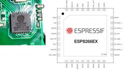
    Image of ESP8285 board and ESP8266EX pinout diagram.
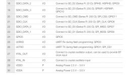
    Here is full GPIO list, as per datasheet:
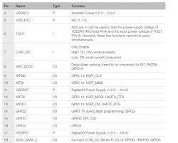
    ESP8266 GPIO pin list with type and function.
    Extract from ESP8266 datasheet showing a list of pins and their functions.
    And then, in Paint, you can map pins one by one, like that;
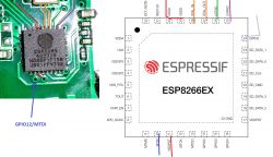
    Close-up of an ESP8285 circuit board and ESP8266EX pinout diagram.
    From a brief glance, it seems that GPIO12/MTDI and GPIO15/MTDO and maybe GPIO5 may be routed somewhere. I can also see U0TXD, U0RXD, etc routed but it's normal, its for programming header... same as GPIO0, but it's still worth to check that.

    Have you managed to flash Tasmota already to this device?

    You can continue to check pins just like I've shown, the method I've used can be very helpful

    Added after 1 [minutes]:

    Do you have a multimeter?
    Helpful post? Buy me a coffee.
  • #3 20825628
    divadiow
    Level 34  
    oh wow. that's amazing. thank you!

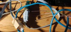
    I'll macro the whole board and trace all the pins. I think it's too small to attempt direct connection to the chip, even with my dodgy sewing needle usb-rs232 cable, which I've not yet tested,
    CH304 USB-DB9 -> Cisco DB9-RJ45 -> RJ45 straight coupler -> RJ45 UTP head cut off -> sewing needles

    Close-up of a makeshift cable: a USB-DB9 cable connected to wires ending in sewing needles.

    lol. I'll have to steady the pins with a giant blob of blu-tack or something.

    No Tasmota on this device yet. Tuya-convert says it's patched of course.
    I do have a multimeter, but I've not used it yet. Just starting out.
  • Helpful post
    #4 20825642
    spin55
    Level 17  
    I have used this to flash NEO sockets and it is quite effective.

    Close-up of colorful wires connected to test probes.
  • ADVERTISEMENT
  • #5 20825666
    divadiow
    Level 34  
    good to know my rig is in with a chance!
  • #6 20825770
    p.kaczmarek2
    Moderator Smart Home
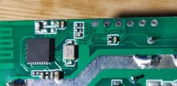
    If there is no Tasmota on this device yet, you also need to figure out the connector for flashing.
    Printed circuit board with visible traces, components, and solder pads.
    1. Use multimeter to check which pin is GND, it should be connected to ground (-) of electrolytic capacitors
    2. Use multimeter to check which pin is 3.3V, it should be connected to positive terminal of electrolytic capacitors or 3.3V of ESP8266
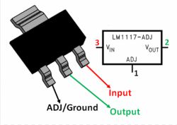
    For points 1 and 2, if there is AMS1117-3.3V on board, you can also use this for reference:
    Diagram showing the pins of the LM1117-ADJ voltage regulator.
    3. Then you need to identify GPIO0 and RX and TX. Again, you can just look at the traces and try to identify where they go.

    The ground will be usually the large copper pool, but it's better to check it anyway. It seems there are 6 pads on the photo, not 5, but you need only 5.
    Helpful post? Buy me a coffee.
  • ADVERTISEMENT
  • #7 20837850
    divadiow
    Level 34  

    I think I've given up. Is it possible anyone can work it out from pictures alone?
  • ADVERTISEMENT
  • #8 20837857
    p.kaczmarek2
    Moderator Smart Home
    I can try, but to be clear, you haven't flashed Tasmota yet?

    Do you have a multimeter?
    Helpful post? Buy me a coffee.
  • #9 20837873
    divadiow
    Level 34  

    I have not flashed Tasmota. I do have a multimeter but have yet to get to grips with it. :/
  • #10 20838026
    p.kaczmarek2
    Moderator Smart Home
    Do you know how to make a continuity test? The one that beeps when you connect two probes together?
    Helpful post? Buy me a coffee.
  • #11 20838242
    divadiow
    Level 34  
    I think I've done it with a continuity test between the esp chip pins and each of the circular factory pads in a row down the side.

    will do it properly later and maybe attempt a flash.

    Portion of a circuit board with several round pads and traces.
  • #12 20838336
    p.kaczmarek2
    Moderator Smart Home
    I think we need to know first which pad is VDD (3.3V), as I said in previous post:
    https://www.elektroda.com/rtvforum/topic4016183.html#20825770
    Helpful post? Buy me a coffee.
  • #13 20851678
    divadiow
    Level 34  
    I bricked it somehow. There seems to be continuity between GND and TX, RX and VCC somehow, I've isopropyl swabbed the board and have checked pins under a macro lens. Oh well. I've ordered more, though there's no guarantee it'll be the same, though I hope it is because I'd like to complete a flash/dump on this particular design.
  • #14 20851760
    p.kaczmarek2
    Moderator Smart Home
    Can you post a photo of the board now? What are the resistances between those pins?
    Helpful post? Buy me a coffee.
  • #15 20851887
    divadiow
    Level 34  

    I'll pull it out of the recycling bag I have and check.

    The board currently looks the same as I have not soldered anything. I was using my sewing needle/ CH340 USB-DB9 cable before I got a proper USB-TTL adapter with 3.3v and now I have bdm pogo pins :)
  • Helpful post
    #16 20942630
    Hgo11
    Level 6  

    Hello,

    I got the same module - I did the measurements and successfully flashed Tasmota.

    See pins below (order from ESP chip):
    GND
    RST
    GPIO0
    TX
    RX
    3V3

    Electronic module with visible pins and a note on paper.
  • #17 20942664
    divadiow
    Level 34  
    ah very good. I never got another one like this in all my trying, so didn't get to play more after bricking it.

    I know what to do now too ;)

    Added after 1 [hours] 11 [minutes]:

    Which store did you buy it from?
  • Helpful post
    #18 20942957
    Hgo11
    Level 6  

    Aliexpress, digital store - each for $1.99, haven't seen them since. All came with different chips. Wi-Fi smart switch modules and sensor from a digital store.

Topic summary

The discussion revolves around identifying the pinout of an ESP8285 10A generic smart WiFi module purchased from AliExpress. The user struggles to find specific PCB markings and seeks assistance in determining the pinouts. Responses suggest referring to the ESP8266 datasheet for GPIO pin mapping and using a multimeter to identify GND and 3.3V connections. Users share their experiences with flashing Tasmota firmware, troubleshooting methods, and the importance of continuity testing. One participant successfully flashed Tasmota and provided the pinout: GND, RST, GPIO0, TX, RX, and 3V3. The conversation highlights the challenges of working with these modules and the variability in components from different suppliers.
Summary generated by the language model.
ADVERTISEMENT