logo elektroda
logo elektroda
X
logo elektroda

[Solved] BK7231N Board with BP2525 ACDC: Relay Configuration Issue After Firmware Flash

jozefbadatel 51 3
ADVERTISEMENT
  • #1 21709669
    jozefbadatel
    Level 2  
    BK7231N Board with BP2525 ACDC: Relay Configuration Issue After Firmware Flash
    BK7231N Board with BP2525 ACDC: Relay Configuration Issue After Firmware Flash
    BK7231N Board with BP2525 ACDC: Relay Configuration Issue After Firmware Flash
    BK7231N Board with BP2525 ACDC: Relay Configuration Issue After Firmware Flash
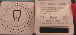
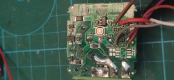
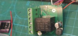
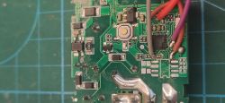
    Hi guys. I have flashed successfully newest fw via BK7231Easy. It has bk7231N and bp2525 AC/DC stepdown converter. FW runs OK. I can reach Wi-Fi and configure. But not able to find proper config. Only thing which works is turning diode on P26 as rel. I am not able to find the way how to switch electromagnetic relay on board (in other words not able find out proper config for this board). I didn't find any board with my layout. I think I do something wrong, but not sure what. I am new in this stuff so there is high probability that I am missing something :) Any guesses? thanks

    Added after 8 [minutes]:

    readResult...-55-44.bin Download(2 MB) backup of original fw
  • ADVERTISEMENT
  • Helpful post
    #2 21709698
    max4elektroda
    Level 21  
    Two possibilities: The WebApp has an "GPIO Doctor" allowing you to set pins high/low, so you can test, which pin will "click" the relay - But for me it quite often crashes.

    My suggestion:
    Go to config page and define some e.g. 5 pins "AlwaysHigh". If after "Save" it "clicks" - the relay switched by one of these pins, try setting pin by pin to "AlwaysLow" to find which one actually switched the relay.
    If it doesn't "click", try next 5 and so on.

    If you don't find it this way, it might be the seldom case of an "Relay_n" (switched on with "Low").
    If you din't find it up to now, all pins are now "AlwaysHigh", so you start the search the other way - setting 5 to "AlwaysLow", if this switches, find the correct one by setting to "AlwaysHigh" one by one.
    Good luck

    Added after 42 [minutes]:

    Or, even simpler, get config from your backup:

    Using Easy UART Flasher will give:
    
    Device configuration, as extracted from Tuya: 
    - Pair/Toggle All Button on P23
    - WiFi LED on P26
    - TglChannelToggle (channel 1) on P6
    - Relay (channel 1) on P7
    Device seems to be using CB2S module, which is using BK7231N.
    And the Tuya section starts, as usual, at 2023424


    Or, e.g. with Linux (or WSL, or busybox ...)
    strings readResult_BK7231N_QIO_bk7231n_2025-01-10-21-55-44.bin  | grep  rl1 | sed "s/,/,\n/ g"
    {rl1_lv:1,
    on_off_cnt:10,
    onoff_rst_m:1,
    onoff_clear_t:10,
    rand_dpid:42,
    net_trig:2,
    onoff_n:3,
    netled1_lv:1,
    jv:102,
    onoff_rst_type:2,
    total_bt_pin:23,
    nety_led:2,
    total_stat:2,
    reset_t:5,
    netled1_pin:26,
    remote_add_dp:49,
    remote_list_dp:50,
    net_type:0,
    inch_dp:44,
    module:CB2S,
    ch_cddpid1:9,
    onoff1:6,
    clean_t:5,
    init_conf:38,
    zero_select:0,
    onoff_type:0,
    series_ctrl:0,
    total_bt_lv:0,
    cyc_dpid:43,
    remote_select:0,
    ch_num:1,
    rl1_pin:7,
    netn_led:2,
    ch_dpid1:1,
    crc:6,
    }ZZZZ


    will also show pin for relay 1 is 7: "rl1_pin:7,"
  • ADVERTISEMENT
  • #3 21709765
    jozefbadatel
    Level 2  
    >>21709698 I tried all of this before my post. BUT recently found that, relay will work only if powered by AC. I did my attempts from plugged external laboratory power supply. Now it works as expected. But nevertheless thanks for your help.
  • #4 21709778
    jozefbadatel
    Level 2  
    Device must be powered from ac through bp2525 to get relay working.
ADVERTISEMENT