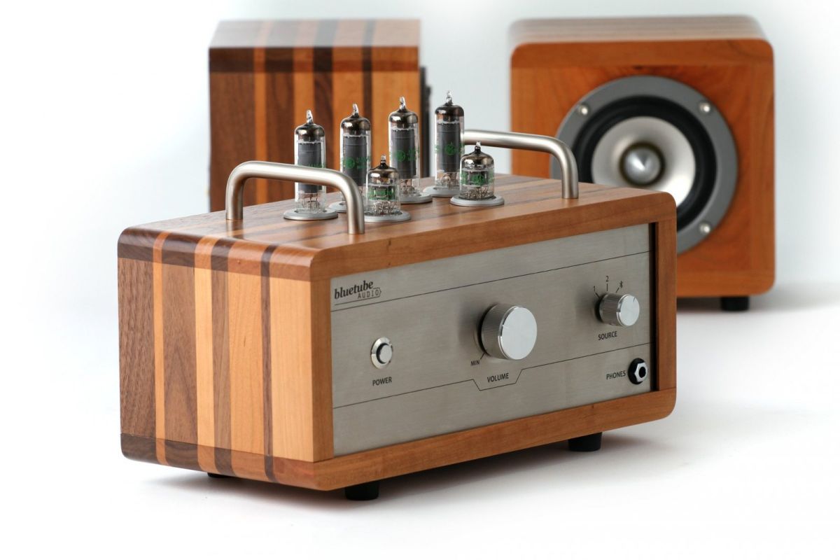





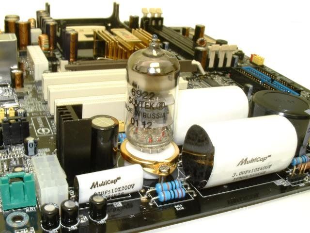
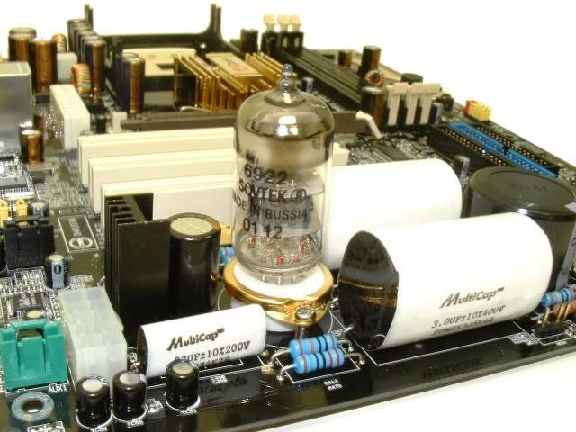
In my previous article on audio sound quality, I discussed germanium transistors in audio amplification circuits, which generated a great deal of interest and lively discussion. In the article below, we will discuss the phenomenon of tube sound, which has recently enjoyed great popularity. A multitude of companies producing tube-based audio equipment have sprung up, and specialist magazines advertise it as the uncompromising choice for ‘true’ audiophiles. This trend has even reached motherboard manufacturers (AOpen AX4B-533 Tube).
I’m at an age where I still remember valve-based receivers, record players and amplifiers. My earliest experiences were with analogue valve designs. And, to be honest, I still enjoy working with valves. They do have certain advantages… but this doesn’t apply to sound quality. To be frank, I’m not in favour of using valves in high-quality audio circuits. Why? Let me explain.
I’ll make it clear straight away that I’m talking solely about audio amplifiers here – that is, the final stage of a home audio system fed by record players, tape recorders or tuners. My suggestions do not apply to amplifier circuits or the shaping of the sound of a guitar or other musical instruments. These devices operate on different principles and are a topic for other articles.
The entire history of audio equipment has been driven by the aim of reproducing a musical track as accurately as possible (Hi-Fi, or High Fidelity). This means that a recording played back by the user at home was intended to sound exactly the same as it did in the recording studio. From an objective point of view, sound quality requires a wide frequency range, uniformity across that range, a low total harmonic distortion (THD) figure, and that is essentially all.
The frequency range of modern music tracks extends from 20 Hz to 20,000 Hz and beyond, but the human ear cannot hear sounds above approximately 15 kHz. Another point is that the wider the frequency response, the better its uniformity. Although this is not always noticeable, every designer or manufacturer strives to achieve the best possible uniformity. And perhaps rightly so.
The THD parameter specifies the percentage of harmonics in an audio signal. As is well known, when a signal passes through a non-linear element, unwanted (in the case of Hi-Fi) harmonics are generated. For example, amplifying a 1 kHz signal results in the generation of spurious signals at frequencies of 2, 3, 4, 5, … kHz. The lower the first harmonic content, the better the THD performance.
What is the situation with valve and transistor amplifiers?
The frequency response of a valve amplifier is limited by the characteristics of the transformer and usually does not exceed 10–50 kHz. Linearity is even worse. Whilst it is reasonably even in the range from 100 to 5000 Hz, it deteriorates significantly both below and above this range. A transformer – at least an output transformer – is essential for matching the high impedance of the valve to the low impedance of the loudspeaker. There are valve circuits without transformers and ways of constructing them, but the laws of physics cannot be circumvented – iron and windings have their own characteristics within a specific frequency range. Whilst the unevenness is practically imperceptible in the 200–5000 Hz range, it deteriorates sharply above or below this range.
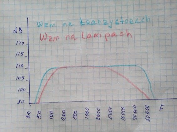
I came across some graphs in the specifications for valve amplifiers showing very good results, but it was an advert for equipment costing as much as a luxury car. So even if it were true, it wouldn’t be cost-effective. Transistor amplifiers have an almost unlimited frequency response — from 20 Hz right up to several MHz — and incomparably better linearity.
As for THD — in high-quality equipment, a level of around 0.1% is acceptable. Lower values are inaudible to the average person. The best valve amplifiers achieve 1–2%. This is something almost anyone can notice. However, according to advocates of valve equipment, this is not a problem, as these distortions are of a different nature and are perceived as pleasant. This means that they are not concerned with faithfully reproducing the original sound. In reality, even Hi-Fi enthusiasts do not hear the original sound in its entirety, because — as one of our readers rightly pointed out — it depends to a large extent on the room in which the music is played. However, given modern circumstances, more and more people are opting for headphones. Tube amplifiers are also used with these.
According to some audio enthusiasts, valve equipment is characterised by a predominance of even harmonics, whilst transistor equipment is characterised by an odd-harmonic bias. This is true, but it applies to all valve equipment and only to cheap – very cheap – transistor amplifiers. Assessing the pleasure derived from the presence of even or odd harmonics is a subjective matter. For example, I would prefer no harmonics, or as few as possible, rather than ‘pleasant’-sounding even harmonics.
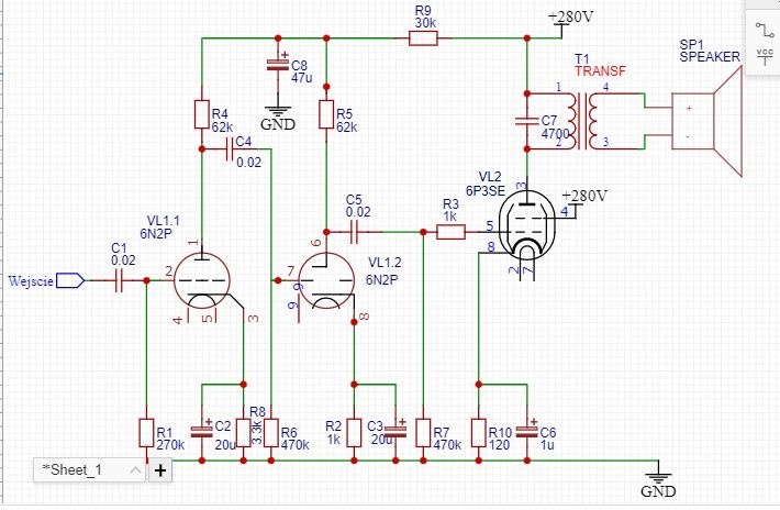
Single-ended amplifier
Double-ended power amplifiers deliver better results in terms of sound quality (both objective and subjective). The diagrams below show configurations with two transformers and with a single transformer.
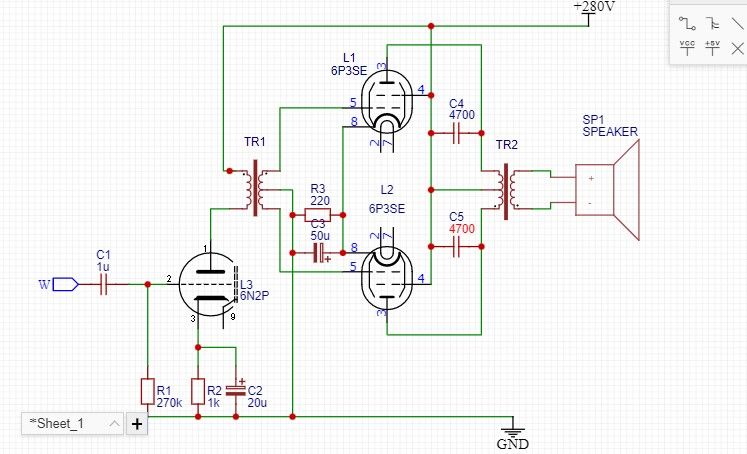
The single-transformer circuit diagram is slightly more complex and requires a minimal tolerance range for the values of components C4–C5, R6–R7 and the parameters of tubes VL2–VL3. This means that it is necessary to select components from several individual units.
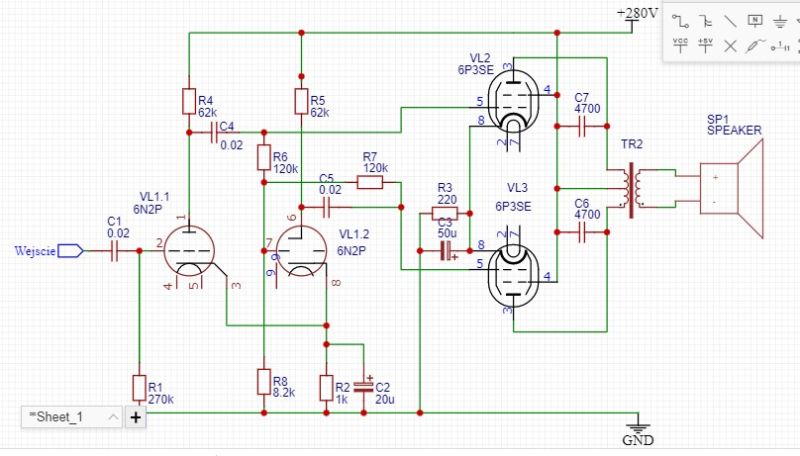
A double-ended amplifier configuration is characterised by 3–4 times greater output power (at the same voltage), which has a beneficial effect on linearity and reduces distortion. Linearity is also improved by the transformer’s operating mode, as the reversal of current direction almost eliminates core saturation. In single-ended amplifiers, direct current always flows through the transformer winding. The same phenomenon occurs in double-ended circuits with two transformers. Given the higher power output of double-ended circuits, a power supply with a higher current capacity should be used.
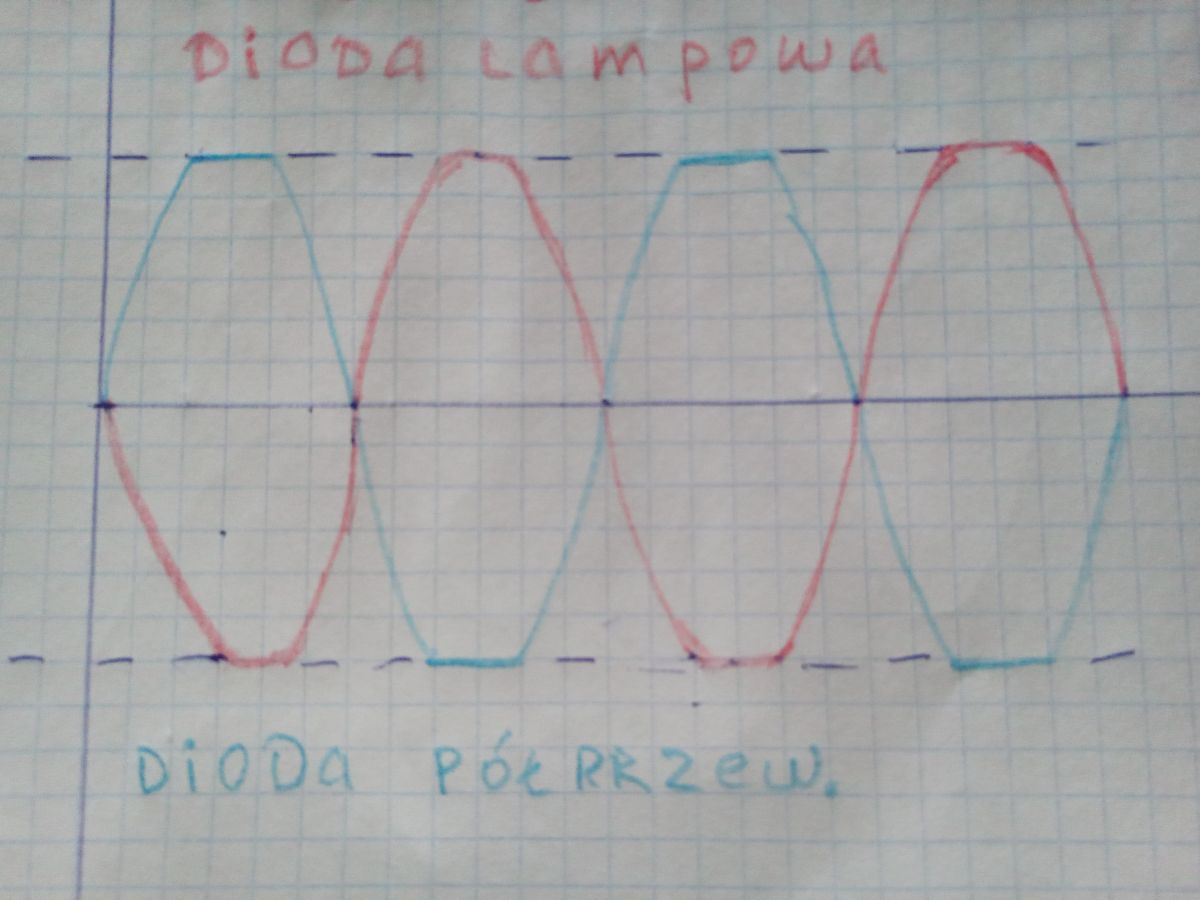
Some audiophiles claim that a valve amplifier loses its advantages if it is not powered by a rectifier using valve diodes (kenotrons). And, surprisingly, I can agree with this — not entirely, but a kenotron does indeed have a positive effect on the sound in certain operating modes. When the amplifier draws high currents, for example at high input signal levels (clipping), the dynamic resistance of a semiconductor diode rises sharply, In the case of a vacuum tube diode, however, it rises slightly more slowly, which means that the resulting distortions have a gentler waveform. This is illustrated in the figure below.
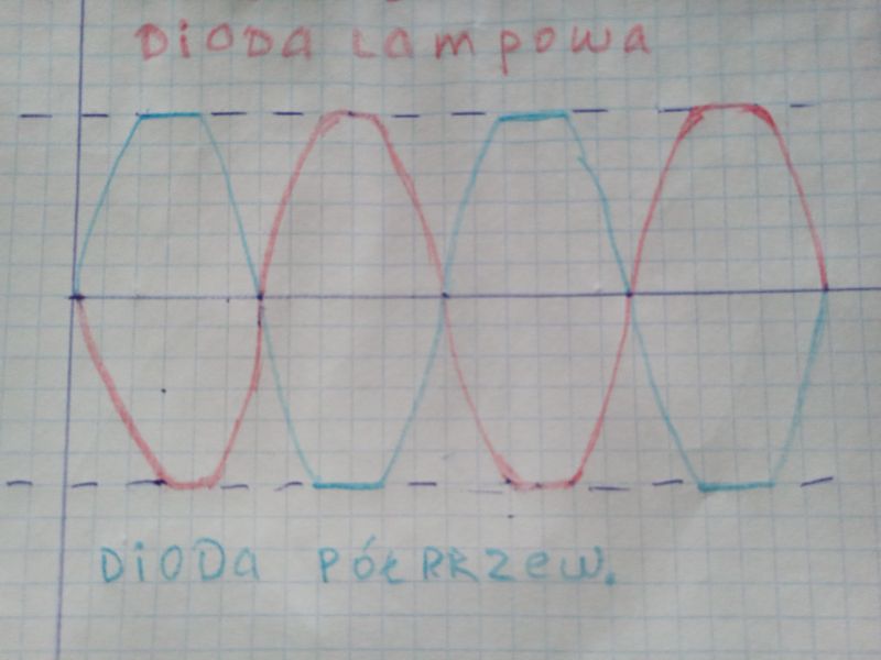
Unfortunately, I am unable to test this theory, but it sounds quite plausible. Another point — it doesn’t really matter, as nobody listens to music in overdrive mode.
Conclusion: despite the above, I’d still like to build a low-power valve amplifier, simply because I like the design of this sort of equipment when the valve is visible and glowing. I’m not enough of an audiophile to tell the difference between the sound of valve and transistor equipment.
I’m at an age where I still remember valve-based receivers, record players and amplifiers. My earliest experiences were with analogue valve designs. And, to be honest, I still enjoy working with valves. They do have certain advantages… but this doesn’t apply to sound quality. To be frank, I’m not in favour of using valves in high-quality audio circuits. Why? Let me explain.
I’ll make it clear straight away that I’m talking solely about audio amplifiers here – that is, the final stage of a home audio system fed by record players, tape recorders or tuners. My suggestions do not apply to amplifier circuits or the shaping of the sound of a guitar or other musical instruments. These devices operate on different principles and are a topic for other articles.
The entire history of audio equipment has been driven by the aim of reproducing a musical track as accurately as possible (Hi-Fi, or High Fidelity). This means that a recording played back by the user at home was intended to sound exactly the same as it did in the recording studio. From an objective point of view, sound quality requires a wide frequency range, uniformity across that range, a low total harmonic distortion (THD) figure, and that is essentially all.
The frequency range of modern music tracks extends from 20 Hz to 20,000 Hz and beyond, but the human ear cannot hear sounds above approximately 15 kHz. Another point is that the wider the frequency response, the better its uniformity. Although this is not always noticeable, every designer or manufacturer strives to achieve the best possible uniformity. And perhaps rightly so.
The THD parameter specifies the percentage of harmonics in an audio signal. As is well known, when a signal passes through a non-linear element, unwanted (in the case of Hi-Fi) harmonics are generated. For example, amplifying a 1 kHz signal results in the generation of spurious signals at frequencies of 2, 3, 4, 5, … kHz. The lower the first harmonic content, the better the THD performance.
What is the situation with valve and transistor amplifiers?
The frequency response of a valve amplifier is limited by the characteristics of the transformer and usually does not exceed 10–50 kHz. Linearity is even worse. Whilst it is reasonably even in the range from 100 to 5000 Hz, it deteriorates significantly both below and above this range. A transformer – at least an output transformer – is essential for matching the high impedance of the valve to the low impedance of the loudspeaker. There are valve circuits without transformers and ways of constructing them, but the laws of physics cannot be circumvented – iron and windings have their own characteristics within a specific frequency range. Whilst the unevenness is practically imperceptible in the 200–5000 Hz range, it deteriorates sharply above or below this range.
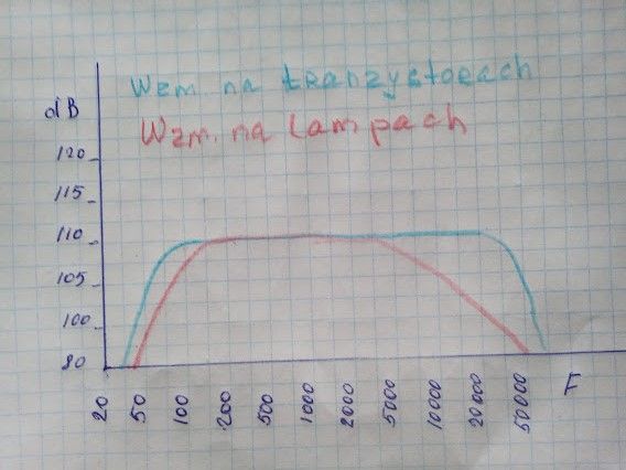
I came across some graphs in the specifications for valve amplifiers showing very good results, but it was an advert for equipment costing as much as a luxury car. So even if it were true, it wouldn’t be cost-effective. Transistor amplifiers have an almost unlimited frequency response — from 20 Hz right up to several MHz — and incomparably better linearity.
As for THD — in high-quality equipment, a level of around 0.1% is acceptable. Lower values are inaudible to the average person. The best valve amplifiers achieve 1–2%. This is something almost anyone can notice. However, according to advocates of valve equipment, this is not a problem, as these distortions are of a different nature and are perceived as pleasant. This means that they are not concerned with faithfully reproducing the original sound. In reality, even Hi-Fi enthusiasts do not hear the original sound in its entirety, because — as one of our readers rightly pointed out — it depends to a large extent on the room in which the music is played. However, given modern circumstances, more and more people are opting for headphones. Tube amplifiers are also used with these.
According to some audio enthusiasts, valve equipment is characterised by a predominance of even harmonics, whilst transistor equipment is characterised by an odd-harmonic bias. This is true, but it applies to all valve equipment and only to cheap – very cheap – transistor amplifiers. Assessing the pleasure derived from the presence of even or odd harmonics is a subjective matter. For example, I would prefer no harmonics, or as few as possible, rather than ‘pleasant’-sounding even harmonics.
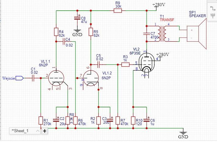
Single-ended amplifier
Double-ended power amplifiers deliver better results in terms of sound quality (both objective and subjective). The diagrams below show configurations with two transformers and with a single transformer.
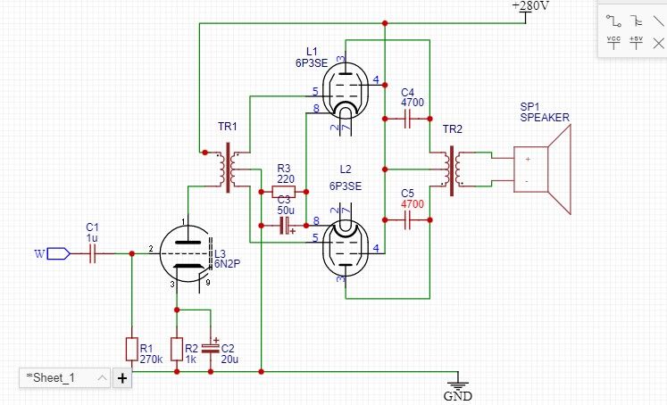
The single-transformer circuit diagram is slightly more complex and requires a minimal tolerance range for the values of components C4–C5, R6–R7 and the parameters of tubes VL2–VL3. This means that it is necessary to select components from several individual units.
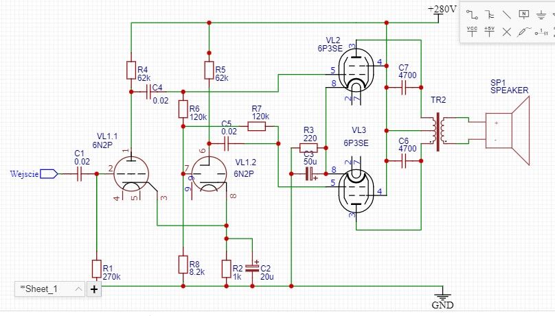
A double-ended amplifier configuration is characterised by 3–4 times greater output power (at the same voltage), which has a beneficial effect on linearity and reduces distortion. Linearity is also improved by the transformer’s operating mode, as the reversal of current direction almost eliminates core saturation. In single-ended amplifiers, direct current always flows through the transformer winding. The same phenomenon occurs in double-ended circuits with two transformers. Given the higher power output of double-ended circuits, a power supply with a higher current capacity should be used.
Some audiophiles claim that a valve amplifier loses its advantages if it is not powered by a rectifier using valve diodes (kenotrons). And, surprisingly, I can agree with this — not entirely, but a kenotron does indeed have a positive effect on the sound in certain operating modes. When the amplifier draws high currents, for example at high input signal levels (clipping), the dynamic resistance of a semiconductor diode rises sharply, In the case of a vacuum tube diode, however, it rises slightly more slowly, which means that the resulting distortions have a gentler waveform. This is illustrated in the figure below.
Unfortunately, I am unable to test this theory, but it sounds quite plausible. Another point — it doesn’t really matter, as nobody listens to music in overdrive mode.
Conclusion: despite the above, I’d still like to build a low-power valve amplifier, simply because I like the design of this sort of equipment when the valve is visible and glowing. I’m not enough of an audiophile to tell the difference between the sound of valve and transistor equipment.
Cool? Ranking DIY