





[BK7238] [T1-S3] [CHT8310] TH01 WiFi Temperature & Humidity Sensor
Hi,
i sucessfully flashed openBeken onto these TH01 temperature sensors which uses a T1-S3 Module.
![[BK7238] [T1-S3] [CHT8310] How to configure pins on TH01 T & H sensor after OpenBeken flash?](https://obrazki.elektroda.pl/7163498500_1783429284_thumb.jpg "[BK7238] [T1-S3] [CHT8310] How to configure pins on TH01 T & H sensor after OpenBeken flash?")
![[BK7238] [T1-S3] [CHT8310] How to configure pins on TH01 T & H sensor after OpenBeken flash?](https://obrazki.elektroda.pl/1731447700_1783429320_thumb.jpg "[BK7238] [T1-S3] [CHT8310] How to configure pins on TH01 T & H sensor after OpenBeken flash?")
![[BK7238] [T1-S3] [CHT8310] How to configure pins on TH01 T & H sensor after OpenBeken flash?](https://obrazki.elektroda.pl/6315226000_1783429440_thumb.jpg "[BK7238] [T1-S3] [CHT8310] How to configure pins on TH01 T & H sensor after OpenBeken flash?")
![[BK7238] [T1-S3] [CHT8310] How to configure pins on TH01 T & H sensor after OpenBeken flash?](https://obrazki.elektroda.pl/1674823200_1783429727_thumb.jpg "[BK7238] [T1-S3] [CHT8310] How to configure pins on TH01 T & H sensor after OpenBeken flash?")
![[BK7238] [T1-S3] [CHT8310] How to configure pins on TH01 T & H sensor after OpenBeken flash?](https://obrazki.elektroda.pl/2237139800_1783429662_thumb.jpg "[BK7238] [T1-S3] [CHT8310] How to configure pins on TH01 T & H sensor after OpenBeken flash?")
It is a battery powered device and the flashing steps were rather difficult because it goes back to its sleep mode quickly and terminats it's connections.
![[BK7238] [T1-S3] [CHT8310] How to configure pins on TH01 T & H sensor after OpenBeken flash?](https://obrazki.elektroda.pl/5970736500_1783429353_thumb.jpg "[BK7238] [T1-S3] [CHT8310] How to configure pins on TH01 T & H sensor after OpenBeken flash?")
I found out that the button on this device keeps the chip from falling "asleep".
So I had to set the baudrate up (9600 -> 1500000) so the transfer got done faster and during the flashing process (read or write) keep clicking the physical button every secound or so to keep the device from falling asleep.
The connection was setup with my USB2TTL - CH340 adapter and i put 3.3VCC, GND, TX1 and RX1 according to the pinlayout.
![[BK7238] [T1-S3] [CHT8310] How to configure pins on TH01 T & H sensor after OpenBeken flash?](https://obrazki.elektroda.pl/7318071300_1783431403_thumb.jpg "[BK7238] [T1-S3] [CHT8310] How to configure pins on TH01 T & H sensor after OpenBeken flash?")
I had to switch RX, TX vice versa, so to say i switched it a couple of times so it matches correctly to give me a correct output signal.
Then i reset it while powered on with everything connected with the CEN/RST pin with GND to bring it into "download/flashing mode"
BK7231GUIFlashTool-build-378 - BK73123Flasher for Windows was used for that which worked fine for chiptype BK7238 (T1).
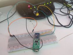
This way it sucessfully flashed the openBK firmware on the device and it opened its Hotspot.
--
Now i face the issue that i have no clue about the pin configuration on the webinterface.
I made a firmware dump of the device before and tried to extract the Config from it but it only says:
Sorry, no meaningful pins data found. This device may be TuyaMCU or a custom one with no Tuya config data.
Baud keyword found, this device may be TuyaMCU or BL0942. Baud value is 9600
No module information found.
Device internal platform - T1, equals BK7238.
And the Tuya section starts at 2052096 (0x1F5000), which is a default T1/XR806 and some T34/BK7231N offset.
It is printed CH8310_SCL and CHT8310_SDA on the PCB of the board so i assume its using the CHT83XX driver.
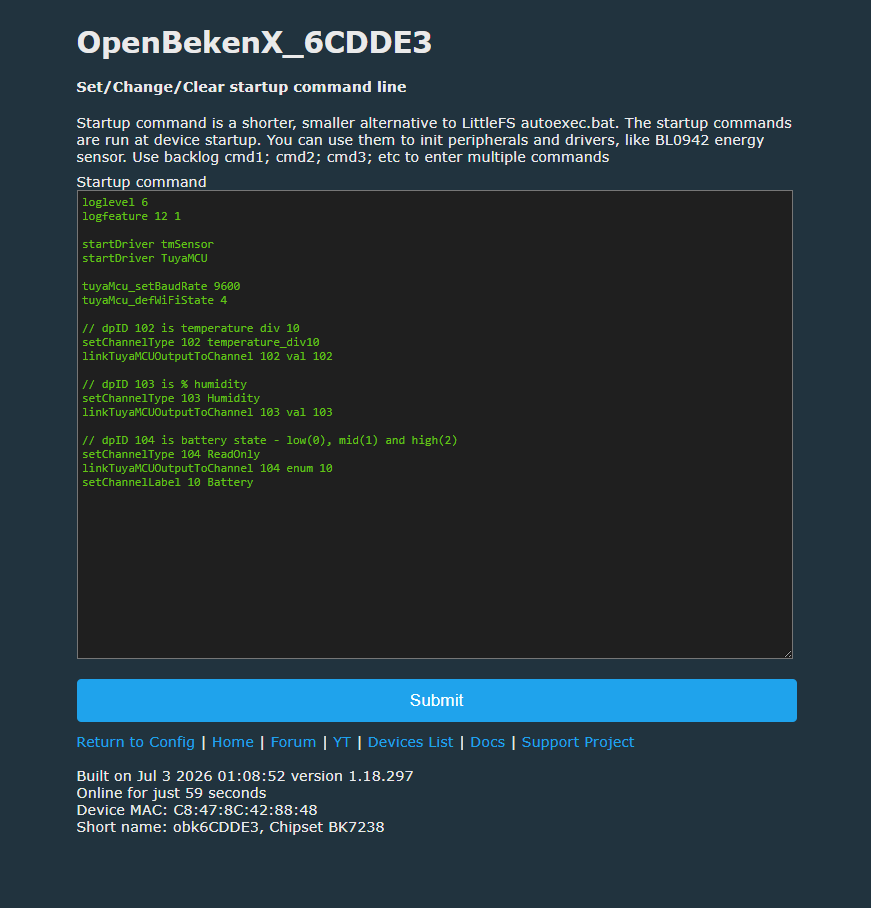
I want the device to display the Temperature, Humidity, Battery Level readings and maybe have the Button as well as the LED of the device working.
Can someone with more knowledge help me figure out the Pin configuration for these devices?
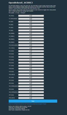
--
Datasheet T1-S3:
https://developer.tuya.com/en/docs/iot/T1-3S-Module-Datasheet?id=Keesax53r0r2d
I do have another device with its original firmware
If someone has an idea or can help me figure out the pin configuration mybe with TuyaMCUAnalyzer-v0.5 would be greatly appreciated.
Can you upload clear photos of both sides of the PCB, especially the traces/labels from CHT8310_SCL, CHT8310_SDA, the button, LED and battery measurement circuit to the T1-S3 module pins?
I've attached photos of both sides of the PCB.
Which OpenBeken build/version did you flash, and did you already try any pin roles in the webinterface, for example CHT83XX SCL/SDA, Button, LED or ADC/Battery?
I did try these two firmwares:
OpenBK7238_QIO_1.18.297.bin
OpenBK7238_QIO_1.18.297_battery.bin
Hi,
i sucessfully flashed openBeken onto these TH01 temperature sensors which uses a T1-S3 Module.
![[BK7238] [T1-S3] [CHT8310] How to configure pins on TH01 T & H sensor after OpenBeken flash?](https://obrazki.elektroda.pl/7163498500_1783429284.jpg "[BK7238] [T1-S3] [CHT8310] How to configure pins on TH01 T & H sensor after OpenBeken flash?")
![[BK7238] [T1-S3] [CHT8310] How to configure pins on TH01 T & H sensor after OpenBeken flash?](https://obrazki.elektroda.pl/1731447700_1783429320.jpg "[BK7238] [T1-S3] [CHT8310] How to configure pins on TH01 T & H sensor after OpenBeken flash?")
![[BK7238] [T1-S3] [CHT8310] How to configure pins on TH01 T & H sensor after OpenBeken flash?](https://obrazki.elektroda.pl/6315226000_1783429440.jpg "[BK7238] [T1-S3] [CHT8310] How to configure pins on TH01 T & H sensor after OpenBeken flash?")
![[BK7238] [T1-S3] [CHT8310] How to configure pins on TH01 T & H sensor after OpenBeken flash?](https://obrazki.elektroda.pl/1674823200_1783429727.png "[BK7238] [T1-S3] [CHT8310] How to configure pins on TH01 T & H sensor after OpenBeken flash?")
![[BK7238] [T1-S3] [CHT8310] How to configure pins on TH01 T & H sensor after OpenBeken flash?](https://obrazki.elektroda.pl/2237139800_1783429662.png "[BK7238] [T1-S3] [CHT8310] How to configure pins on TH01 T & H sensor after OpenBeken flash?")
It is a battery powered device and the flashing steps were rather difficult because it goes back to its sleep mode quickly and terminats it's connections.
![[BK7238] [T1-S3] [CHT8310] How to configure pins on TH01 T & H sensor after OpenBeken flash?](https://obrazki.elektroda.pl/5970736500_1783429353.jpg "[BK7238] [T1-S3] [CHT8310] How to configure pins on TH01 T & H sensor after OpenBeken flash?")
I found out that the button on this device keeps the chip from falling "asleep".
So I had to set the baudrate up (9600 -> 1500000) so the transfer got done faster and during the flashing process (read or write) keep clicking the physical button every secound or so to keep the device from falling asleep.
The connection was setup with my USB2TTL - CH340 adapter and i put 3.3VCC, GND, TX1 and RX1 according to the pinlayout.
![[BK7238] [T1-S3] [CHT8310] How to configure pins on TH01 T & H sensor after OpenBeken flash?](https://obrazki.elektroda.pl/7318071300_1783431403.png "[BK7238] [T1-S3] [CHT8310] How to configure pins on TH01 T & H sensor after OpenBeken flash?")
I had to switch RX, TX vice versa, so to say i switched it a couple of times so it matches correctly to give me a correct output signal.
Then i reset it while powered on with everything connected with the CEN/RST pin with GND to bring it into "download/flashing mode"
BK7231GUIFlashTool-build-378 - BK73123Flasher for Windows was used for that which worked fine for chiptype BK7238 (T1).
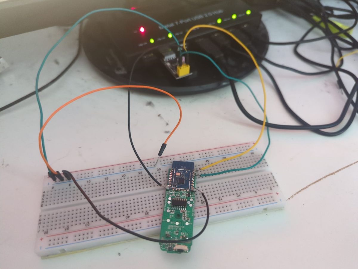
This way it sucessfully flashed the openBK firmware on the device and it opened its Hotspot.
--
Now i face the issue that i have no clue about the pin configuration on the webinterface.
I made a firmware dump of the device before and tried to extract the Config from it but it only says:
Sorry, no meaningful pins data found. This device may be TuyaMCU or a custom one with no Tuya config data.
Baud keyword found, this device may be TuyaMCU or BL0942. Baud value is 9600
No module information found.
Device internal platform - T1, equals BK7238.
And the Tuya section starts at 2052096 (0x1F5000), which is a default T1/XR806 and some T34/BK7231N offset.
It is printed CH8310_SCL and CHT8310_SDA on the PCB of the board so i assume its using the CHT83XX driver.
I want the device to display the Temperature, Humidity, Battery Level readings and maybe have the Button as well as the LED of the device working.
Can someone with more knowledge help me figure out the Pin configuration for these devices?
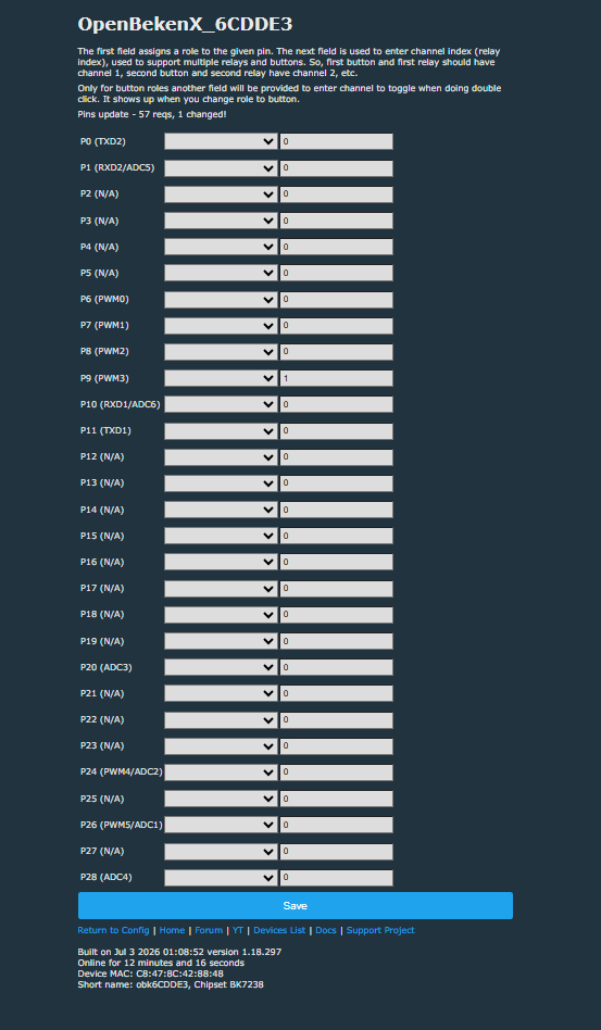
--
Datasheet T1-S3:
https://developer.tuya.com/en/docs/iot/T1-3S-Module-Datasheet?id=Keesax53r0r2d
I do have another device with its original firmware
If someone has an idea or can help me figure out the pin configuration mybe with TuyaMCUAnalyzer-v0.5 would be greatly appreciated.
Can you upload clear photos of both sides of the PCB, especially the traces/labels from CHT8310_SCL, CHT8310_SDA, the button, LED and battery measurement circuit to the T1-S3 module pins?
I've attached photos of both sides of the PCB.
Which OpenBeken build/version did you flash, and did you already try any pin roles in the webinterface, for example CHT83XX SCL/SDA, Button, LED or ADC/Battery?
I did try these two firmwares:
OpenBK7238_QIO_1.18.297.bin
OpenBK7238_QIO_1.18.297_battery.bin
![[BK7238] [T1-S3] [CHT8310] How to configure pins on TH01 T & H sensor after OpenBeken flash?](https://obrazki.elektroda.pl/2048953900_1783446674.png "[BK7238] [T1-S3] [CHT8310] How to configure pins on TH01 T & H sensor after OpenBeken flash?")
![[BK7238] [T1-S3] [CHT8310] How to configure pins on TH01 T & H sensor after OpenBeken flash?](https://obrazki.elektroda.pl/1545803000_1783454446.png "[BK7238] [T1-S3] [CHT8310] How to configure pins on TH01 T & H sensor after OpenBeken flash?")
![[BK7238] [T1-S3] [CHT8310] How to configure pins on TH01 T & H sensor after OpenBeken flash?](https://obrazki.elektroda.pl/5317810200_1783454421.png "[BK7238] [T1-S3] [CHT8310] How to configure pins on TH01 T & H sensor after OpenBeken flash?")
![[BK7238] [T1-S3] [CHT8310] How to configure pins on TH01 T & H sensor after OpenBeken flash?](https://obrazki.elektroda.pl/6720635700_1783454192.png "[BK7238] [T1-S3] [CHT8310] How to configure pins on TH01 T & H sensor after OpenBeken flash?")
