

logo elektroda
logo elektroda
X
logo elektroda
Dostępna jest polska wersja

Czy wolisz polską wersję strony elektroda?

Nie, dziękuję Przekieruj mnie tam

How do you create an active load on an ESP32 using a power transistor and current control?

uasic 66 2
ADVERTISEMENT
Treść została przetłumaczona polish » english Zobacz oryginalną wersję tematu
  • Clarify source current limit and shunt measurement approach

    #1 21936235
    uasic
    Level 11  
    Posts: 11
    Hello.

    I want to build an active load module for the ESP-32. From what I’ve gathered, you need to connect a power transistor to the source of the device under test.
    The ESP-32 code itself isn’t a problem, but the thing is… how to physically build the module, and how it’s supposed to work.

    The project is interesting in that there’s hardly anything about it online, and it’s needed to regulate the maximum current.

    I’d appreciate some help with this.
    What voltage and current should this active load have, i.e. what is the voltage range of the source under test and what maximum current/power do you want to regulate?
    At the moment, I need to set it to 5 A at 12 V, but it could be a universal device for, say, 100–150 W.
    Is the load intended to operate linearly as a regulated ‘resistor’/constant current, or simply switch the load on and off via PWM, and do you plan to measure the current via a shunt connected to the ESP32?
    I’m not entirely sure. I’m trying to determine the maximum current the device can supply (this involves regulating the maximum current supplied by the step-down converter – controlled by a potentiometer). I need to measure the current it’s supplying (because I want to limit it to a certain upper limit).
  • ADVERTISEMENT
  • Op-amp controlled constant-current load with shunt sensing

    #2 21936322
    CHCl3
    Level 9  
    Posts: 37
    Rate: 13
    uasic wrote:
    I need to measure the current it supplies

    So you need a constant-current load with an adjustable current setting.

    In my opinion, using a microcontroller to build an active load is a bit odd, but it’s up to you. You could build one using a single operational amplifier.
    You’ll need a reference voltage source, an operational amplifier, a shunt (resistor) for measuring current, and a power transistor. The operational amplifier compares the voltage across the shunt with the reference voltage (e.g. set by a potentiometer) and controls the transistor so that it conducts the set current.
    If you really want to, you could replace the reference voltage source with a microcontroller; PWM and a simple integrator filter. But you’ll probably still need an operational amplifier to control the transistor.

    I am currently building the circuit from the link below, but using slightly different components due to availability. I need it to diagnose a power supply I am repairing.
    https://danyk.cz/zatez2_en.html

    Most of the voltage (and power) from the measured source is dissipated across the power transistor. This should be a Darlington transistor with a high β or a MOSFET. You need to find one with suitable ratings for current, voltage and SOAR. I’m currently using a TIP122, but in practice it probably won’t withstand more than 30–40 W; for now, that’s enough for me.
    The rest of the power is dissipated across the shunt resistor; you need to choose one with a margin.
  • MOSFET-based active load with ESP32 current control

    #3 21936366
    gklub
    Level 34  
    Posts: 1782
    Help: 306
    Rate: 762
    uasic wrote:
    This is about regulating the maximum current supplied by the step-down converter

    It couldn’t be simpler ;)
    It’s not a very precise load, but combined with an ammeter it should be sufficient.
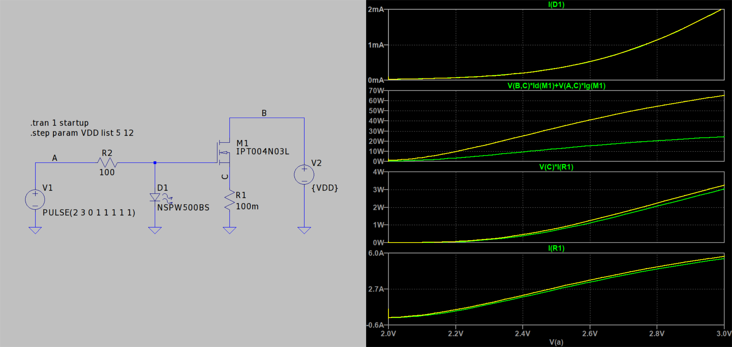
    LTspice schematic with IPT004N03L MOSFET and plots of current and power for VDD 5 and 12 V
    Essentially, you need a variable resistor and an ammeter.
    You can’t buy a 100W potentiometer, but a MOSFET can act as a substitute.
    Its ‘resistance’ is controlled by the gate voltage.
    Note how little the current depends on the supply voltage – here 5 and 12V.
    In such a circuit, the permissible supply voltage (of the converter under test) is limited by the permissible gate voltage – see the catalogue.
    The transistor used here, with a suitable heat sink, will handle 300W.
    A source resistor, e.g. 100 mΩ/10 W – theoretically, it could be omitted, but it makes control much easier.
    Resistor R2 and the diode limit the gate voltage and thus the power transistor’s current to safe levels, even in the event of incorrect voltage control at point A.
    You supply the control voltage from the ESP to point A, replacing V2 in the converter.
    You can use a different, similar transistor, but you’ll need to set the control voltage range for the specific unit you’re using.
    If you want a better solution – see Howlwnd’s source.
    There’s been quite a lot on the forum, including in recent weeks.
ADVERTISEMENT