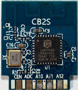
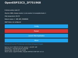
I try to connect a small 3.3 V buzzer to my smart plug with LN822HKI controller in.
I created a small 5 mm x 5 mm board with an AO3401 Mosfet and 47 k resistor across Gate and Source. The buzzer hangs between Drain and GND.
I connected this board to those pins:
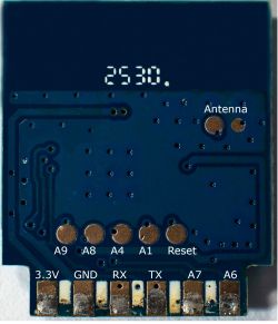
A8, 3.3 V and GND.
After evaluation of the board, there should be sufficient current for the mini buzzer (28 mA), as the AMS1117 3.3 V with BP2525D before, have enough headroom.
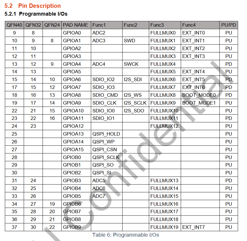
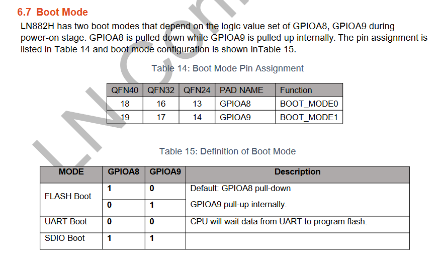
No problem defining pin 8 as rel_n, but as soon as I connect my small board, the application freezes and is no longer reachable via WLAN.
Its no current problem, as I measure stable 3.312 V, which looks even quiet clean on an osci.
Testing the board standalone works perfect: connecting to a 3.3 V source and connecting Gate to GND, the buzzer does its job.
So I have learned that pin 9 left of pin 8 bring the board down for flashing, but I have not read similar things over pin 8.
I can toggle Pin8 without connected buzzer, as soon as I have defined it. The only problem is that once I connect the mini board, the application freezes and does not boot on repowering.
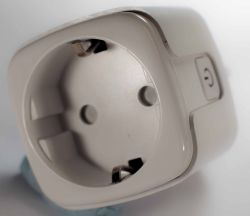
Here are some more pictures of the UPXNBOR-XT03:
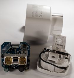
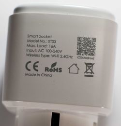
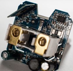
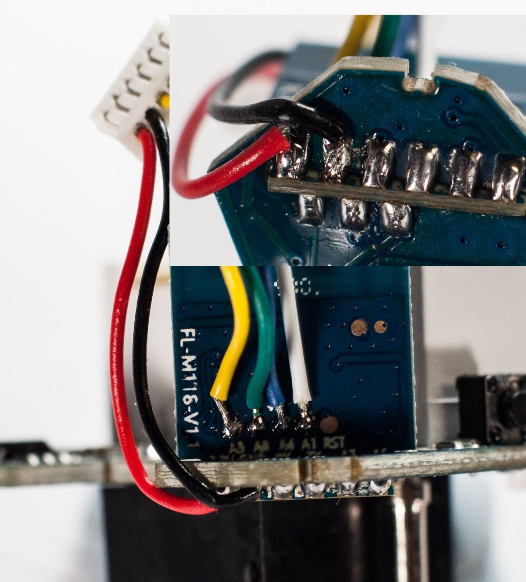
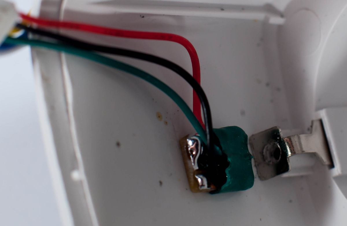
And the pictures of my buzzer installation:
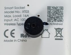
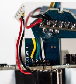
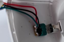
So the question is: Has pin 8 a similar function like pin 9, that freezes the µC?
Added after 13 [minutes]:
Just to explain the buzzer:
The buzzer should sound when a device plugged in is running for longer than configured, and if it is running outside of business hours. Just an acoustic reminder, before silent shutdown after a period of rest.
I created a small 5 mm x 5 mm board with an AO3401 Mosfet and 47 k resistor across Gate and Source. The buzzer hangs between Drain and GND.
I connected this board to those pins:
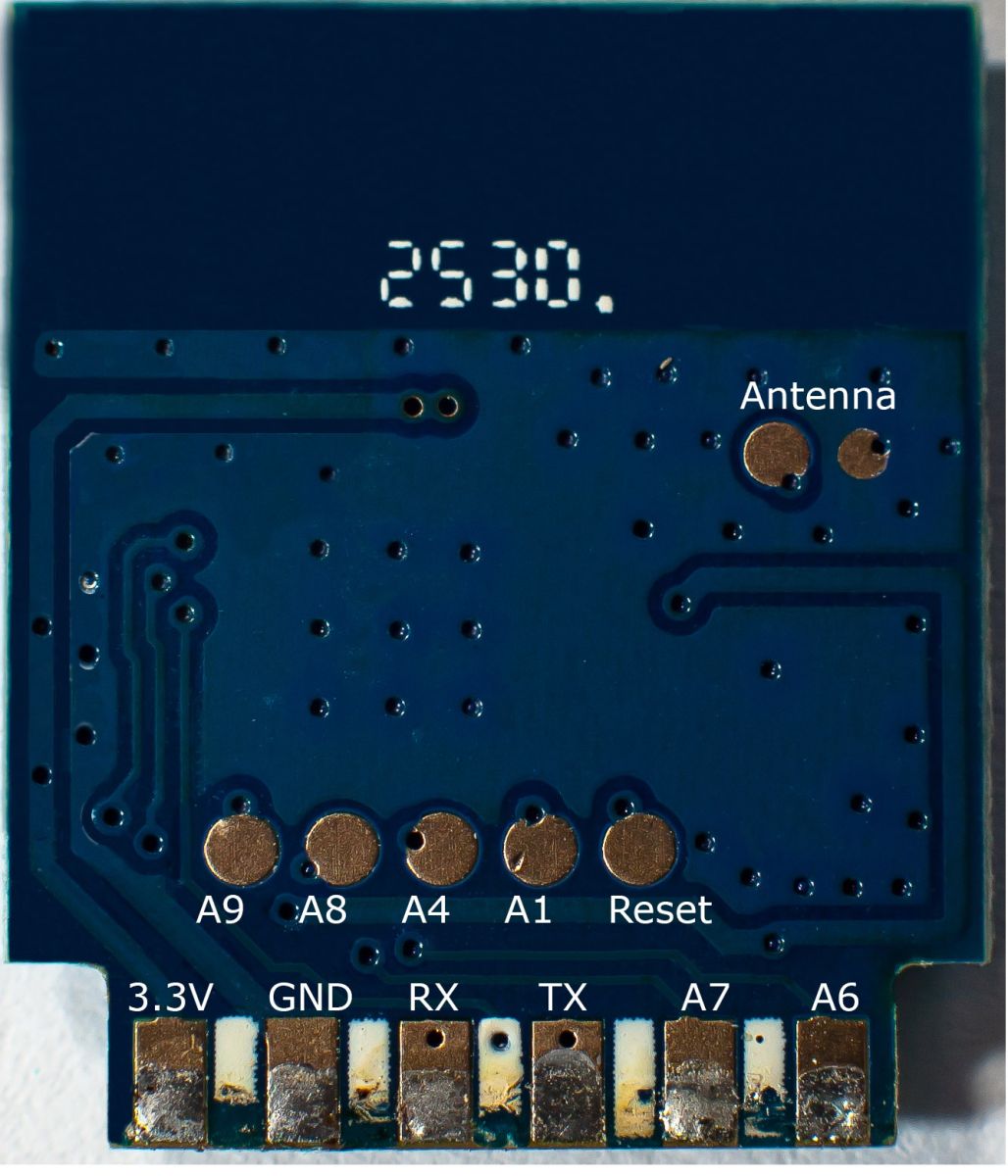
A8, 3.3 V and GND.
After evaluation of the board, there should be sufficient current for the mini buzzer (28 mA), as the AMS1117 3.3 V with BP2525D before, have enough headroom.
No problem defining pin 8 as rel_n, but as soon as I connect my small board, the application freezes and is no longer reachable via WLAN.
Its no current problem, as I measure stable 3.312 V, which looks even quiet clean on an osci.
Testing the board standalone works perfect: connecting to a 3.3 V source and connecting Gate to GND, the buzzer does its job.
So I have learned that pin 9 left of pin 8 bring the board down for flashing, but I have not read similar things over pin 8.
I can toggle Pin8 without connected buzzer, as soon as I have defined it. The only problem is that once I connect the mini board, the application freezes and does not boot on repowering.
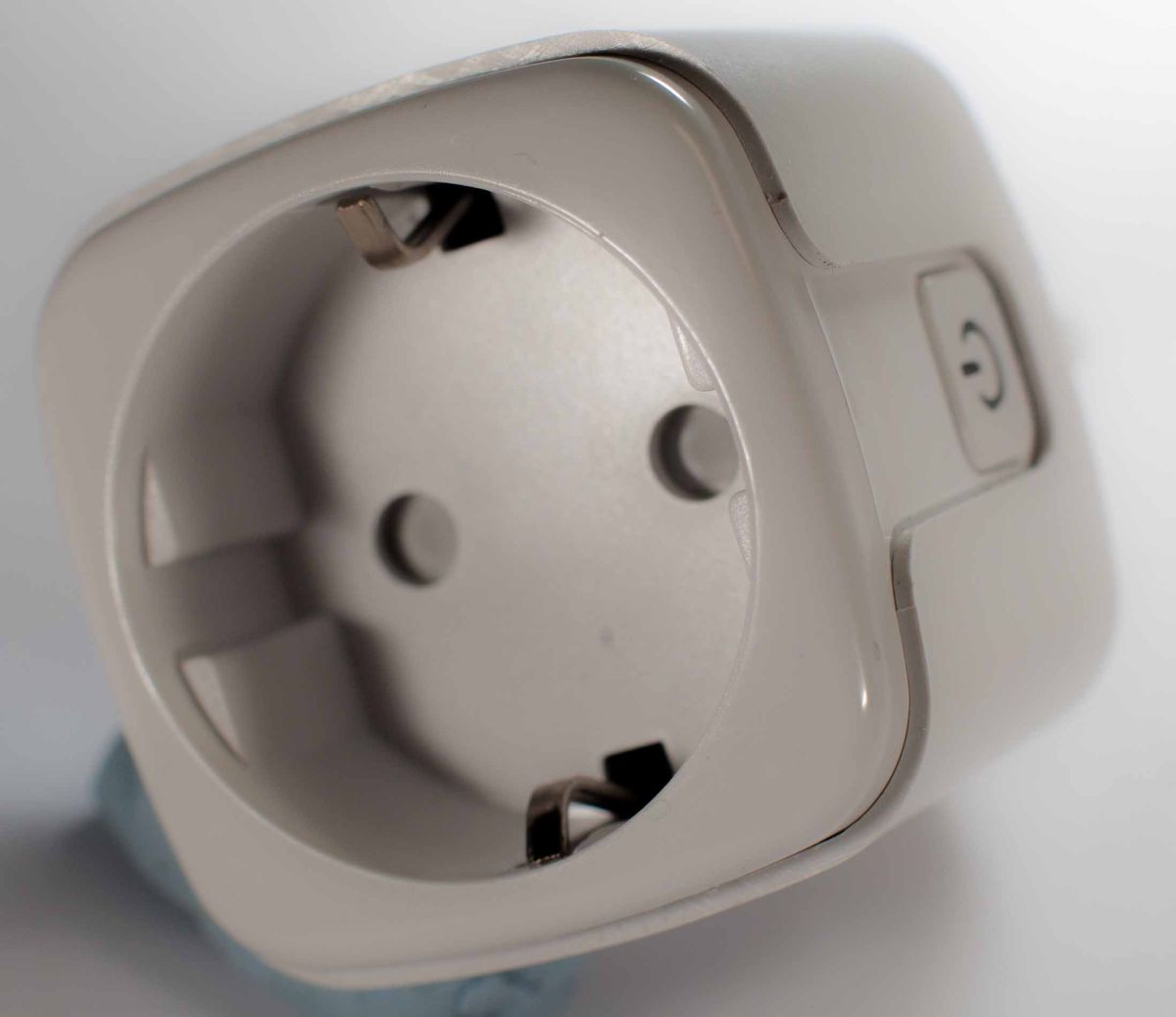
Here are some more pictures of the UPXNBOR-XT03:
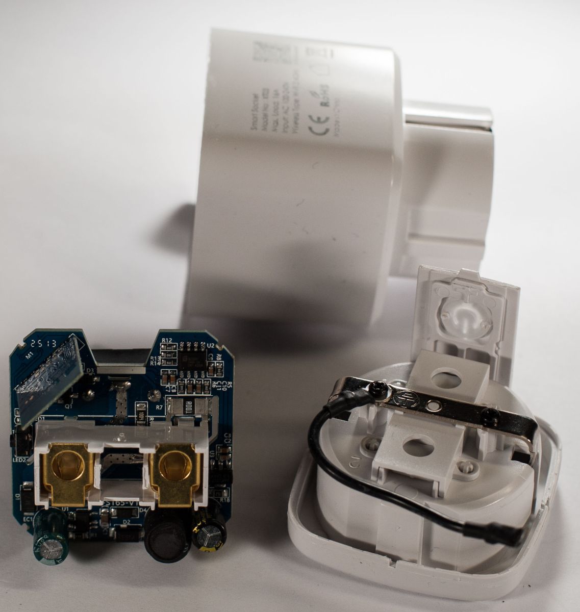
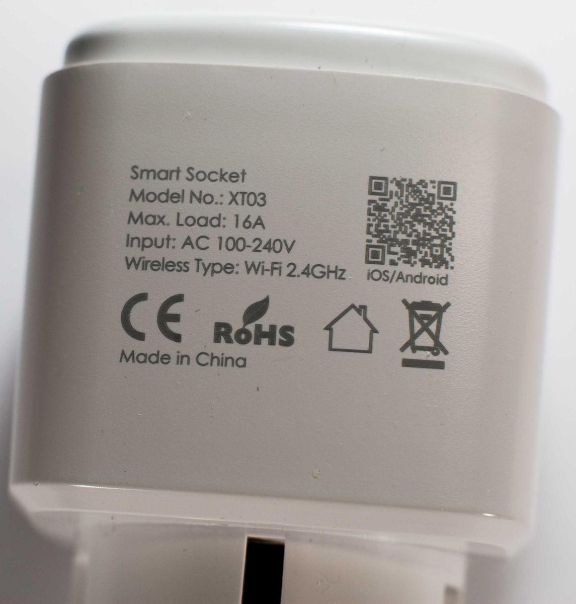
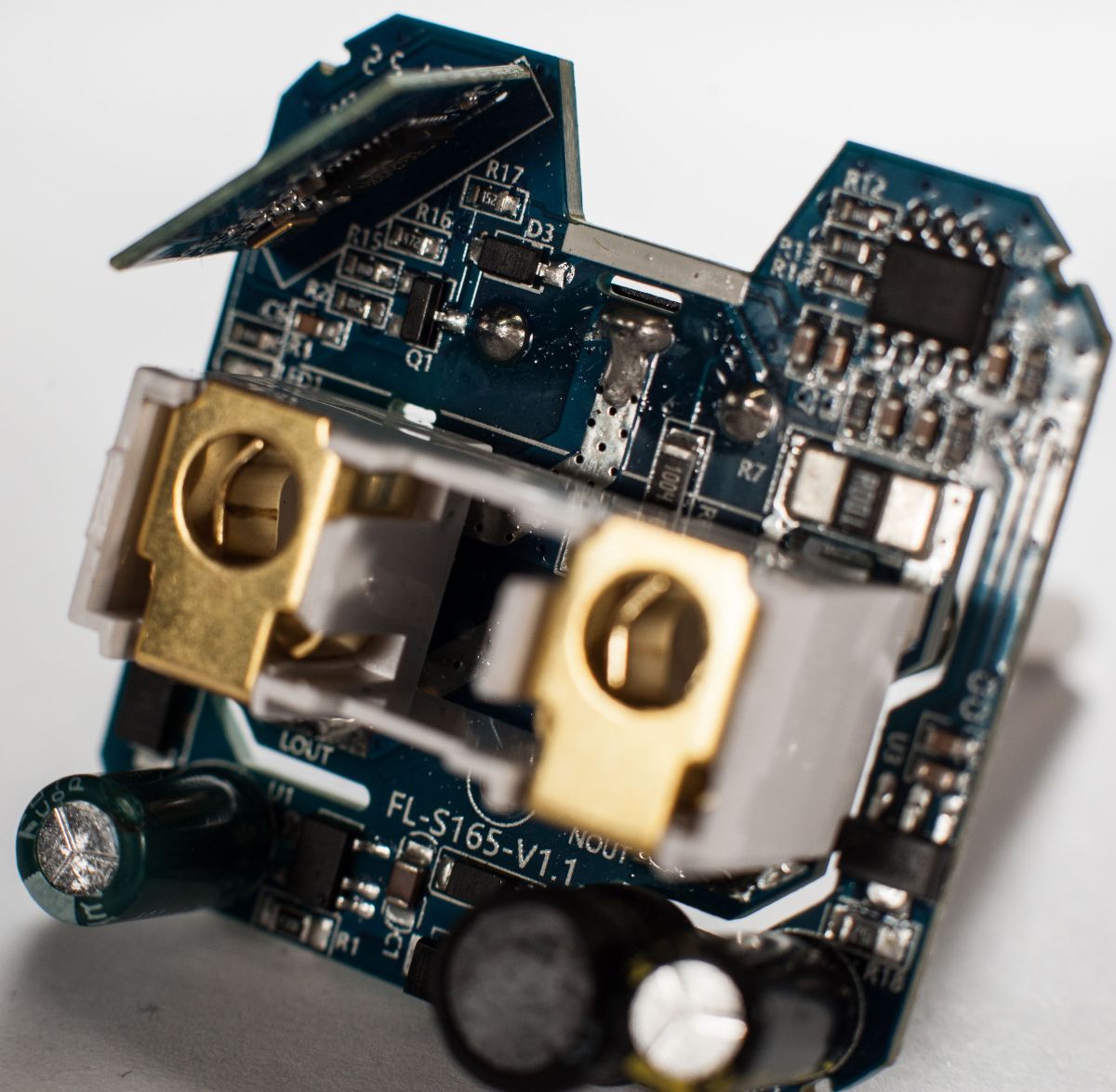
And the pictures of my buzzer installation:
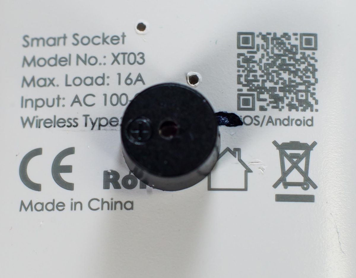
So the question is: Has pin 8 a similar function like pin 9, that freezes the µC?
Added after 13 [minutes]:
Just to explain the buzzer:
The buzzer should sound when a device plugged in is running for longer than configured, and if it is running outside of business hours. Just an acoustic reminder, before silent shutdown after a period of rest.