Already a few years ago I made an analog electronic tachometer (with a tip) and it works without problems in my motorcycle
enduro which is Yamaha XT600, type 3TB, year 1995.
I think that since the design has proven itself "in battle" it will be worth presenting it here.
Why did I make such a modification? Mainly due to the fact that the old mechanical indicator was driven by a cord
from the worm gear in the engine head. Often there was an unsealing of the O-ring which caused oil leaks,
and the link itself also disappointed. The original one is expensive and the poor quality substitutes have not lasted even one season.
I show below step by step how the design and implementation went, I attach a diagram with the values of the elements,
so almost complete data to make such a tachometer on your own.
Almost, because I do not show here the PCB pattern due to the fact that it is dimensioned for the specific housing of my old original meter.
In addition, whoever wants to can use the ready tachometer module and as such adapt it to their needs.
I downloaded the two most important components from it: the CS8190 integrated circuit and the air-core tip drive, and I've done the rest myself.
I will write about this module later.
In this forum, in the automotive section, there is the topic "Tachometer in a moped":
Tachometer in a moped but dozens of answers do not consistently present one concept of the device there, and when the thread of the tachometer module similar to the one described here appears, there is no meaningful explanation of the changes needed to adapt it to specific requirements.
Therefore, I think that here - in the DIY department - showing your own solution will be appropriate and welcome

Well, then.
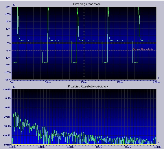
Modifications were made on a motorcycle with a four-stroke, single-cylinder engine, TCI ignition controlled by a microprocessor. It supplies one coil and one spark plug.
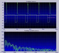
Oscilloscopic measurement showed that the ignition module gives one impulse for every revolution of the crankshaft.
This is how the oscillogram looks like when the engine is idling (about 1500 rpm):
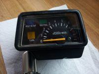
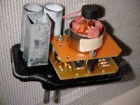
I used the original housing of the tachometer because it also has control lamps.
The dial, which was also preserved, was illuminated by a W5W bulb, but it did not look good.
I decided to change it too.
The maximum reading of the original tachometer is 9000 rpm with a pointer angle of 180 degrees.
It looked like this:
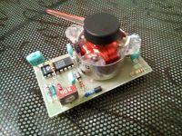
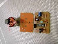
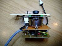
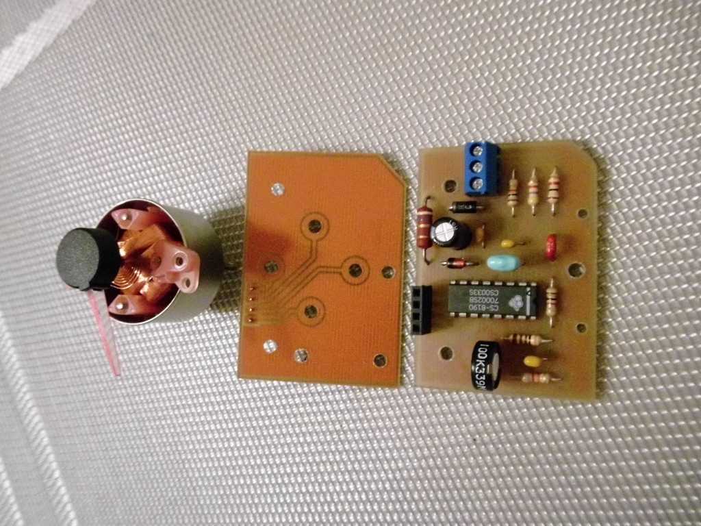
I bought a cluster of clocks from Polonez for 20 zlotys and got a tachometer from it (Lumel MS14)
It is built on the basis of the CS8190 system, which controls the air-core drive. It looks like this:
As I have already mentioned, the module on the board can be adapted by appropriate selection of elements to suit the tachometer's own design.
Air-core itself is easily removable from the plate (four M3 screws) and most importantly - with a relatively hard return spring on the axle.
Thanks to this, it is more resistant to shocks, after all, it was in the Polonez driving on our bad roads years ago.
It will therefore remain to get (or replace) several items.
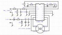
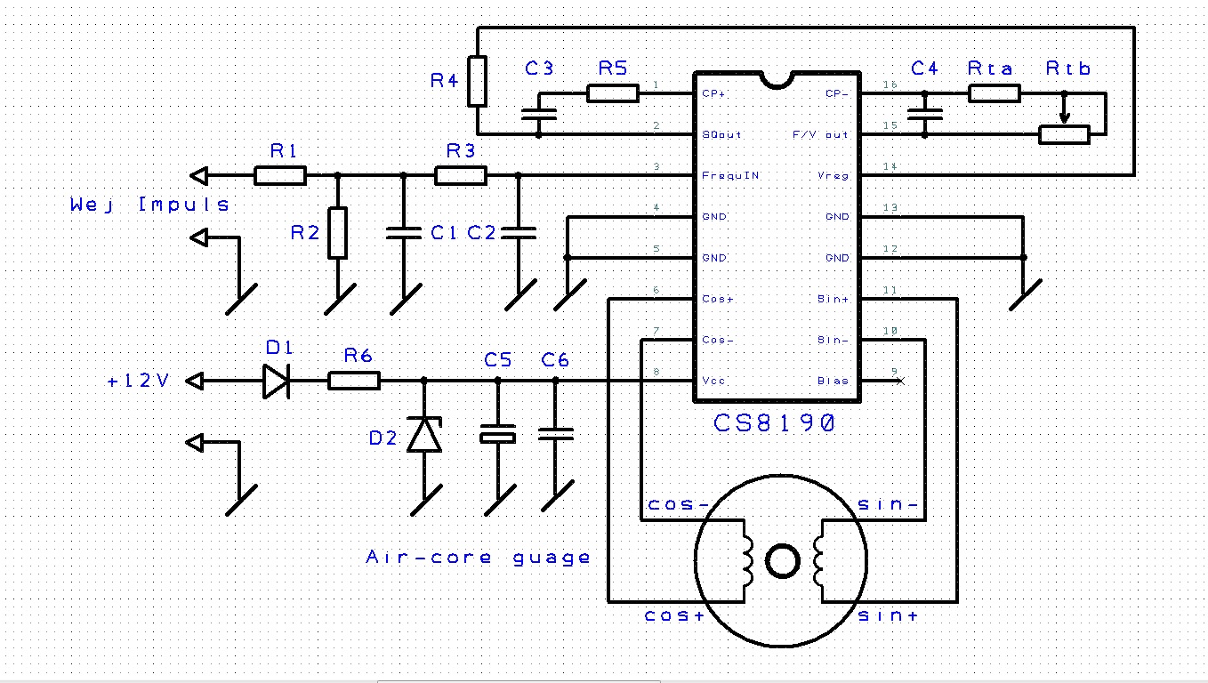
The diagram does not differ much from the application from the catalog note CS8190 and is almost the same as the one from Polonez:
 Assumptions for the project
 1. maximum tip angle is wskazówki = 180 degrees
2. maximum frequency of the input pulse is f = 150 Hz (max revolutions 9000 [rpm] / 60 [sec])
3. Ccp = 4.7 nF
4. R3 = 3 k?
5. R4 = 1 k?
Calculations in the catalog note of the CS8190 integrated circuit the following formula is given for the swing angle of the air-core pointer:
? = 970 xfx Ccp x Rt
so we calculate the value of the resistor Rt from it:
Rt = ? / (970 xfx Ccp) = 180 / (970 x 150 x 4.7) = 263 k?
To be able to correct this value, I split it into a series connection of a resistor Rta = 220 k and a potentiometer Rtb = 100 k
We calculate RC time constants for two cases:
1.Ccp capacitor charging:
(R3 + R4) x Ccp = (1 + 3) x4.7 = 18.8 us
2.Ccp capacitor discharge:
R3 x Ccp = 3x4.7 = 14.1 us
and check if the conditions for the minimum input signal period are met, which is:
Tmin = 1 / fmax = 1/150 Hz = 6.67 ms
Well, the RC time constants calculated above must be less than 10% Tmin (i.e. 667 us) and this is the case here.
We then calculate the value of the C4 capacitor, which is a compromise between the acceptable vibration of the pointer,
and sometimes her reaction to the signal. The catalog note gives the following formula:
C4 = (Ccp x 6.3 V) / ?Vmax
In my design, I assumed that the vibration of the hands were relatively small at the expense of the reaction speed.
I assumed ?Vmax = 30 mV and hence the calculated value:
C4 = (4.7 x 6.3) / 0.03 = 1 uF
The experimental value of the C5 capacitor is yet to be selected if the air-core would be without a return spring (they are such)
My air-core has such a spring, so C5 is completely unnecessary, but I kept it for more reliable filtration of the supply voltage
(C5 = 100 uF and C6 = 100 nF)
Summary of items: R1, R5 = 1 k?
R2 = 4.7 k?
R3 = 10 k?
R4 = 3 k?
R6 = 4,7
Rta = 220 k?
Rtb = 100 k?
C1, C2, C6 = 100 nF
C3 = 4.7 nF
C4 = 1 uF
C5 = 100 uF (25 V)
D1 = np. 1N4001
D2 = Zener 30-50 V
CS8190
Air-core with a coil resistance of about 200 ?
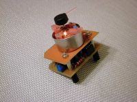
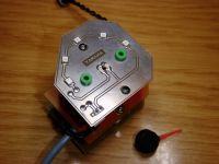
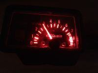
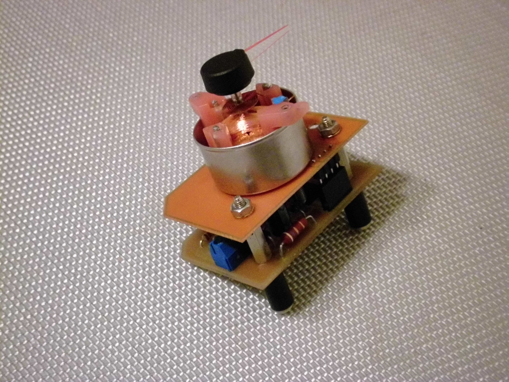
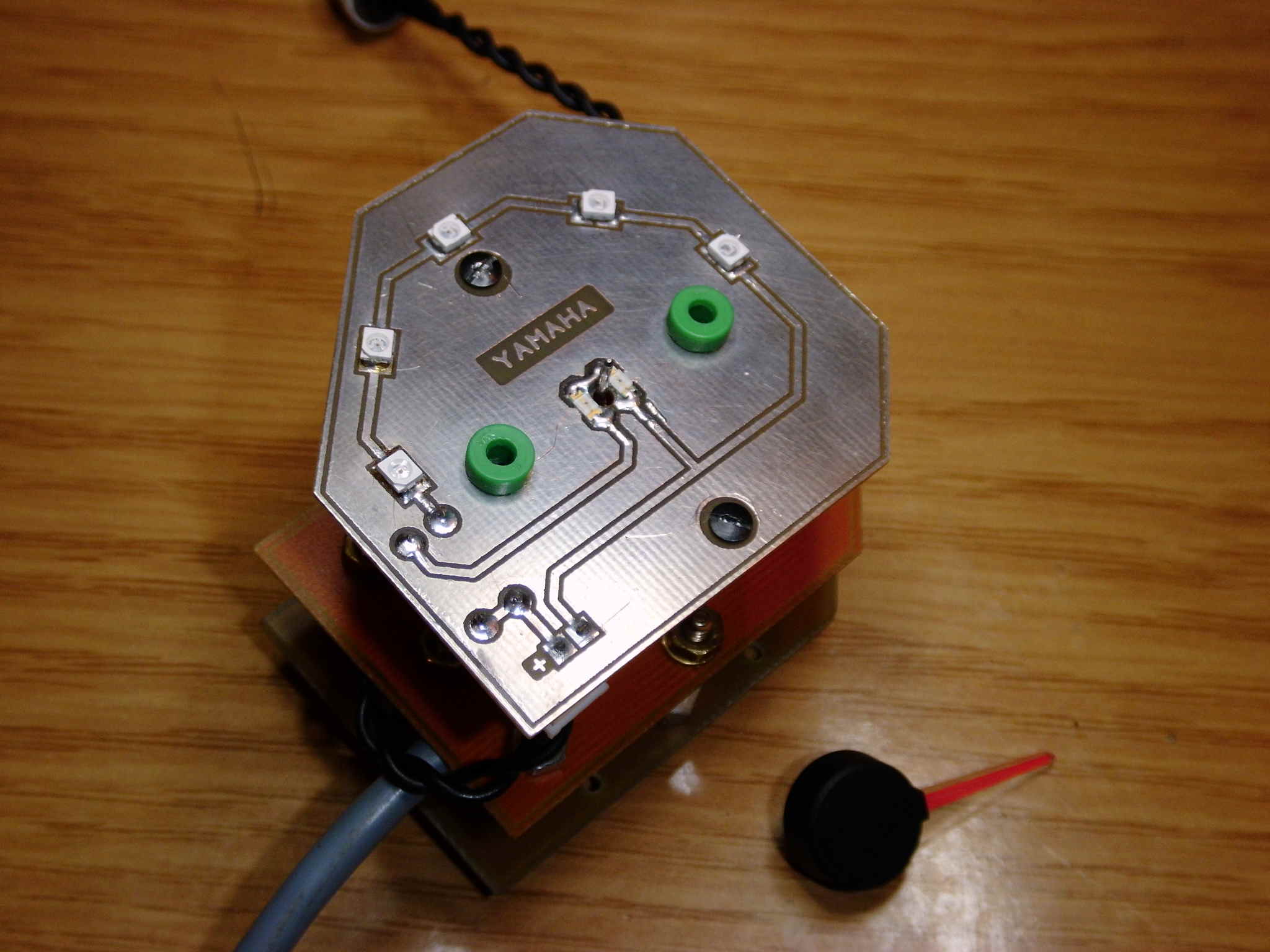
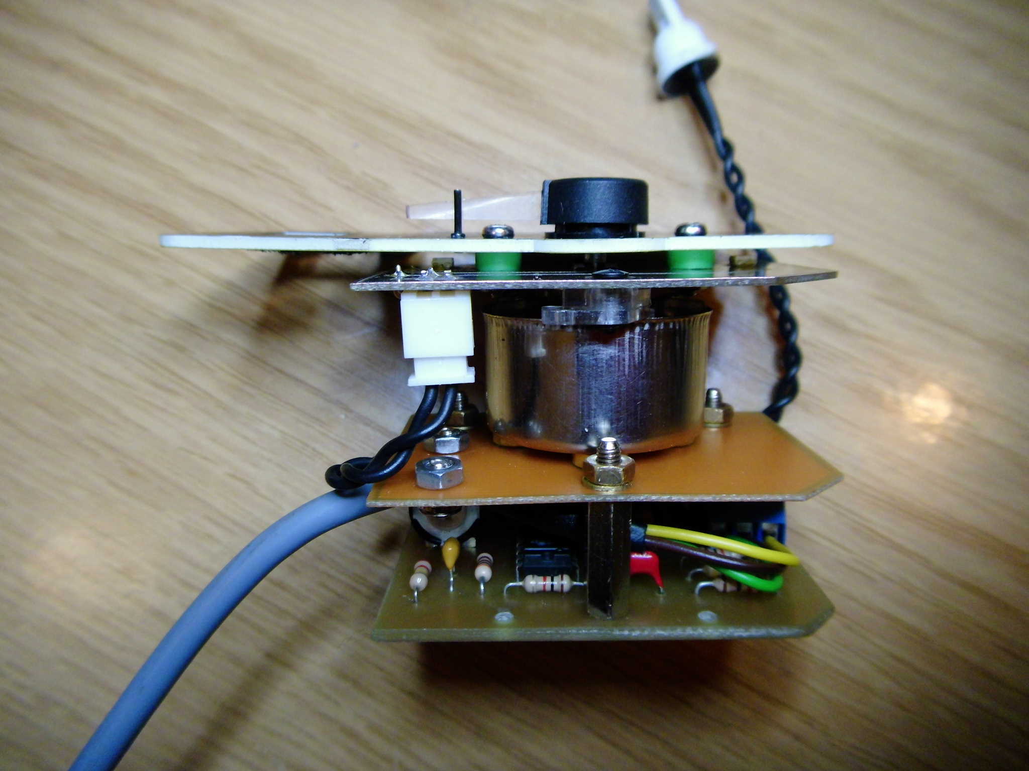
Execution: Three stacked PCBs. The bottom is the main board with all electronic components on board.
The middle one is the base for the air-core, and the top one has SMD LEDs that illuminate the dial and pointer
on red. LEDs are powered from a separate light circuit in the motorcycle.
The power supply to the electronics itself is taken of course "behind the ignition"
The pulse signal comes directly from the ignition module output to the coil (keyed + 12V)
A few photos about the installation of the tiles:
Launching is reduced to connecting the tachometer input to the ignition module output where the signal goes to the coil
ignition and potentiometer adjustment of the indicated RPM so that they are as close to real as possible.
Current consumption about 50mA.
Vibration tips while driving due to shocks are gone, as I mentioned the air-core drive has a strong return spring and it seems to be an exam.


Comments
So you replaced the housing and changed some elements based on the manufacturer's note. From the description I did not deduce that the PCB you made yourself (no description) and the PCB looks well... [Read more]
Very nice design and importantly described exactly. If someone wants to transfer it to a multi-cylinder motorcycle, there will be no problem because it is written how to calculate everything. This backlight... [Read more]
There is nothing in the description about the PCB (iron, chemistry). In the low-budget production version I saw such PCBs, usually copper is tin-coated, but not necessarily. I saw production series without... [Read more]
Tell me exactly what Polonaise these clocks were from? I suspect that not every tachometer was mounted on this CS system. [Read more]
Terrible clinging. The author has carried out work, which he described quite accurately. He made mechanical modifications, took into account the adaptation of the integrated circuit application to work... [Read more]
Give R-MIK a break. This is an outstanding specialist in every field. He did not make such arrangements. Read it yourself this subject . I like the layout, a good way to use parts from the... [Read more]
... and this is what I described here! Thank you for your accurate remarks k9mil and djfarad02 Not every writing here must be a diploma thesis right away as not every diploma thesis is suitable for ...... [Read more]
Everyone used to start and create more or less successful constructions. This one, although simple, is made very carefully. Many of the constructions presented here could be called a makeshift. Returning... [Read more]
The PCB was protected with PVB60 after testing and final seating in the housing. It is quite tight so moisture is unlikely to appear. I attach a short video showing how the tachometer works on my... [Read more]
Is this suitable for diesel? Does anyone know if the signal from the 'W' alternator will be sufficient for the tachometer to operate? PS project great, it will definitely be useful :) [Read more]
CS8190 is basically an f / U converter and should be adaptable to the "W" output of a diesel alternator. The following conditions must be met: - the maximum voltage applied to the system input should... [Read more]
The CS8190 system is an old age, for differential control, with two coils. In newer motorcycles, the tachometer system is based on TB9226, where the number of cylinders is configured with jumpers. Still... [Read more]
Right, CS8190 is old, but it is relatively easy and cheap to obtain from Polonez clocks. It controls the logometer, which is also an advantage, because it is a simple drive and fault-tolerant. The... [Read more]
Do you have datascheet for TB9226 ?? [Read more]
Is it possible to obtain a PCB schematic on a 1: 1 scale, I have a tachometer in xt 600 [Read more]
I used to do several tachometers, the one from the polonaise has a very high pointer inertia. In my opinion, the best ones are AutoGauge. They have regulations for 2, 4, 6 cylinders, and the conversion... [Read more]
If someone have another one already made and working I am willing to buy it ;) I am restoring my yamaha XT600 from 1984 and have broken revmeter (2 of them). I'm in Croatia. Thanks in advance, ... [Read more]