Hello.
Below I present to you a description of a very cheap single-channel rectangular signal generator with adjustable filling. Prices in China start from about $ 0.5 with shipping, in Poland from about PLN 11 with shipping.
The system is sold as a ready-made kit.
Dimensions: 32 x 22 x 15mm.
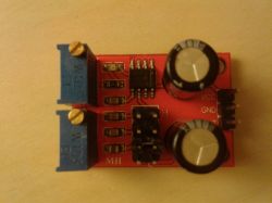
The generator is based on the well-known NE555 chip. The board also has two multi-turn precision potentiometers, where, according to the manufacturer, one is used to regulate the frequency, and the other to regulate the filling of the generated signal.
We also have a three-pin goldpin connector, where we have to provide power - VCC, ground - GND, and we have the output of the generated signal - OUT.
In addition, we also find an LED for signal visualization at the output and a row of double goldpins with a jumper for setting the frequency adjustment ranges. The connector is labeled with the letters L and H, where L is the lowest possible frequency range and H the highest. We have 4 possible ranges to set:
- 1Hz - 50Hz,
- 50Hz - 1kHz,
- 1kHz - 10kHz,
- 10kHz - 200kHz.
Generator power supply in the range 4.5 - 16VDC. According to the manufacturer, the amplitude at the output is in the 4-12VDC range, it depends on the generator supply voltage. The maximum output current according to the manufacturer is 5mA with a 5V supply and 35mA with a 12V supply. According to the NE555 catalog note, it is about 200mA, but you have to take into account that there is also an LED on the board, which also loads the system.
The potentiometer in the upper left corner is used to regulate the duty cycle of the signal - turning it to the left increases the degree of filling, turning it to the right reduces it. The potentiometer in the lower left corner is used to adjust the frequency - by turning it left, we decrease the frequency of the generated waveform, and turn it to the right.
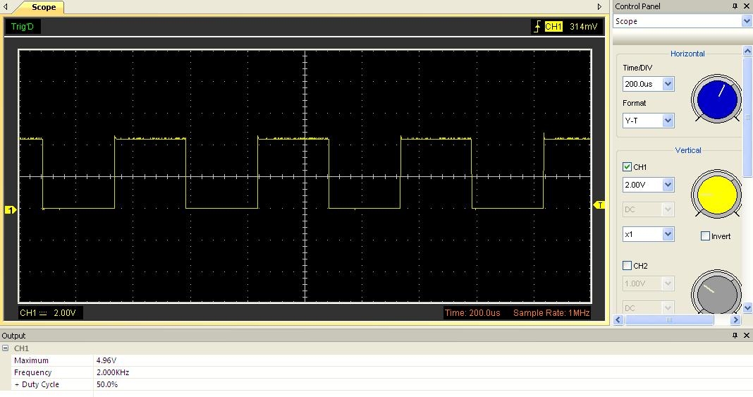
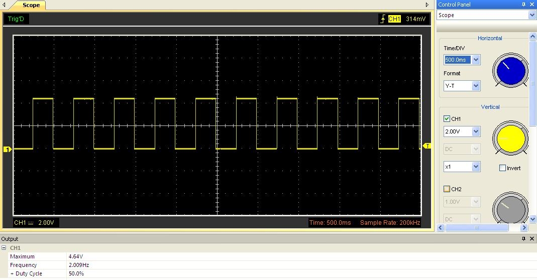
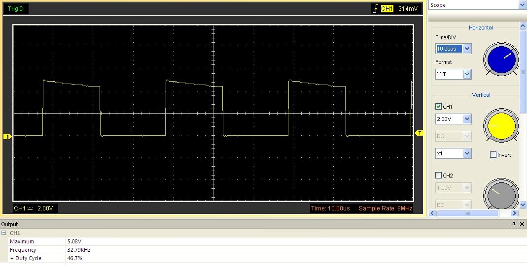
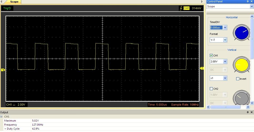
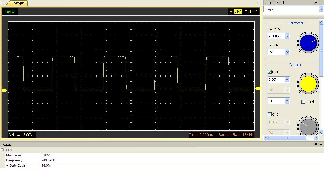
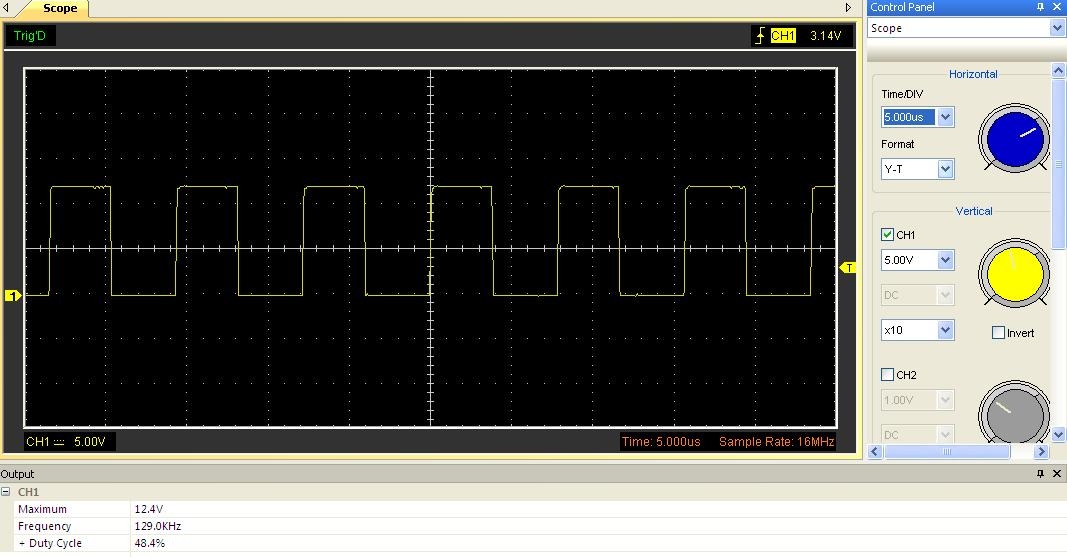
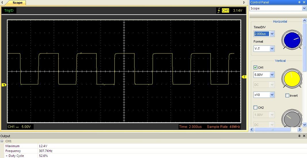
Below are a few waveforms with different power values.
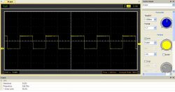


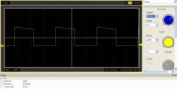

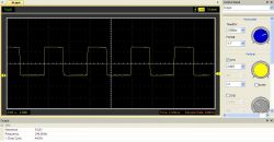

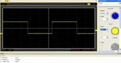
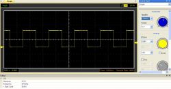

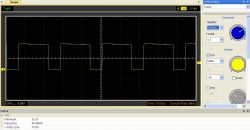
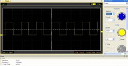

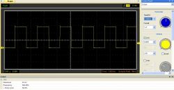
It can be seen that the amplitude at the output is almost the same as the supply voltage of the tested generator. You can see that with about 15V power supply, the amplitude at the output was almost that of the supply voltage, so the manufacturer's data is slightly understated - at least in this particular case.
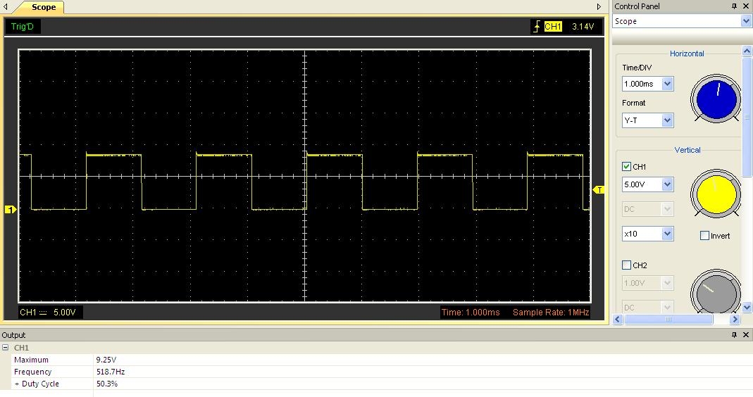
The filling, which was achieved on the tested generator, is in the range of 30-99% (below 30%, the generator output shows a low state, setting the filling potentiometer to the minimum value will give us a 99% filling of the course) and you have to wind up a bit to set what we want, because by turning the knob to change the fill, we also change the frequency. We don't have that big problems with the frequency control potentiometer - here the frequency also changes, but only to a very small extent.
It can also be noticed that the change of the supply level has an impact on the frequency of the generated waveform at the same potentiometer settings, i.e. by increasing the supply voltage, the frequency of the output waveform increases and its filling slightly.
During the generator tests, it was possible to obtain a higher frequency of the generated signal than specified by the manufacturer, but the higher the frequency, the more distorted the signal becomes.
Below is a link to the description of another, more expensive two-channel generator with a three-digit seven-segment display, where it is also possible to adjust both the waveform frequency and the duty cycle.
https://www.elektroda.pl/rtvforum/topic3422908.html#16981517


Comments
Can you ask for a diagram of this wonder? [Read more]
Why do you need a diagram? Ready layout costs much less than if you were to buy each item individually. However, if you have all the components in the proverbial drawer, the diagram can be found... [Read more]
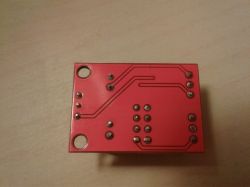
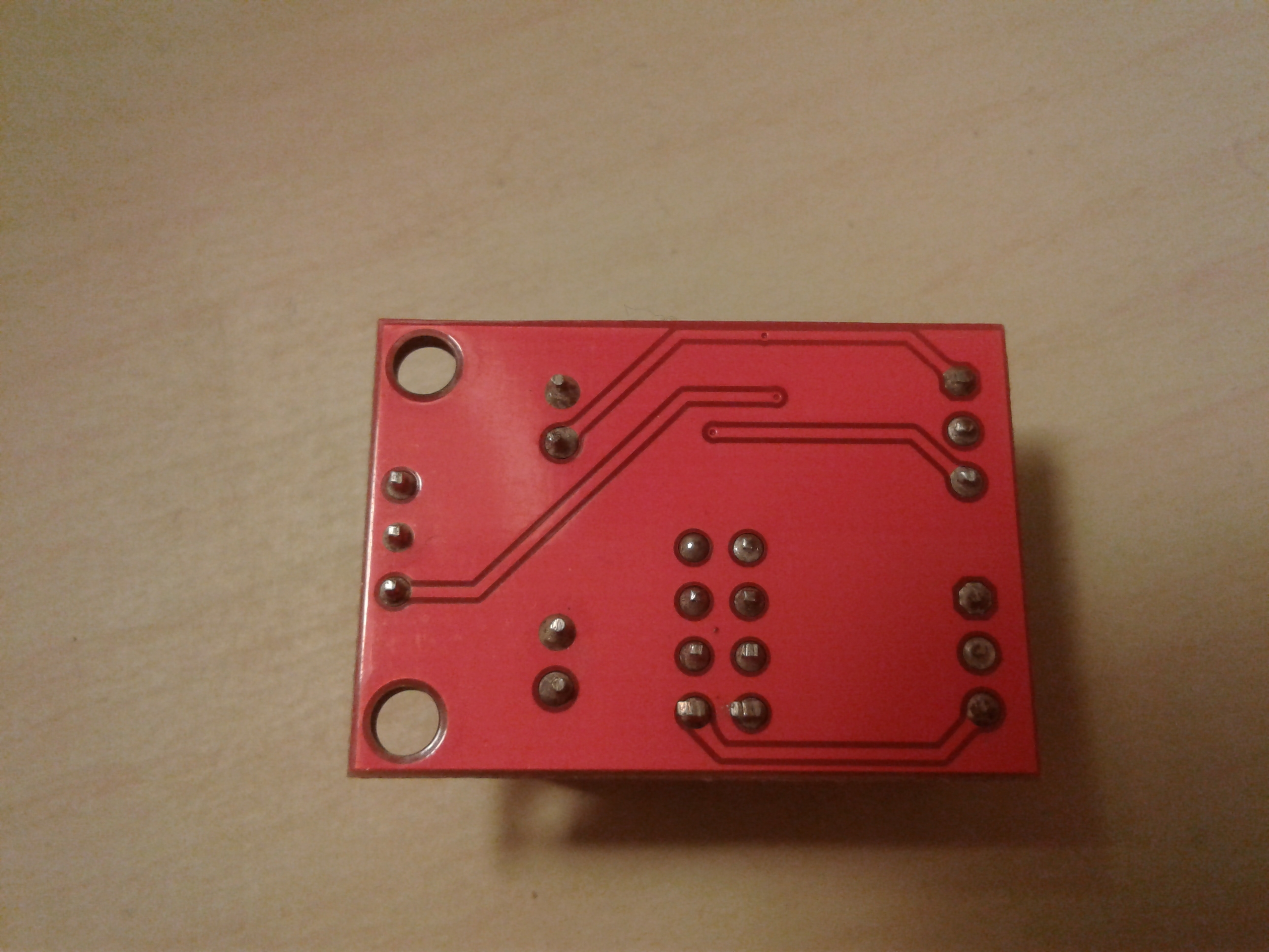
Two PCB layers for such "shit"? [Read more]
Two cheaper than one, or the same price, and the benefits of two layers are much more. [Read more]
Two cheaper than one or the same price What in this project? [Read more]
The prices for the Chinese are the same because they usually only use double-sided cores. With two layers, the size of the PCB can be reduced, thus lowering the cost of the PCB. Two layers are always better... [Read more]
and before: In this project? I doubt it. In this project? And it effectively makes it difficult to desolder the element (e.g. during repair or commissioning) [Read more]
Hello. A simple, but as usual interesting project based on the NE555. This cube will probably never die ... :) Recently, I even had the pleasure of doing something similar at work for PWM control. ... [Read more]
And it's not like you can get 51-99% filling on 555, or something like that? [Read more]
That's right, which is why those signals with less than 50% are so distorted. : / [Read more]
Therefore, I propose to correct this parameter in the description of the module's operation. [Read more]
Scheme: https://obrazki.elektroda.pl/2276734700_1516840571_thumb.jpg [Read more]
Hello The output from this system is several dozen mA, and I need a few hundred, e.g. 0.5A. What's the easiest way to increase this? Is such a circuit on one transistor enough? https://obrazki.elektroda.pl/7581009800_1636121152_thumb.jpg... [Read more]