The project below is a weather station based on a module with ESP8266. There would be nothing special about it that distinguishes it from other such constructions, if not for the optimization of the system in terms of minimizing power consumption. The microcontroller used is not very energy-efficient, so it works on average in battery-powered applications - the ESP8266 with WiFi enabled consumes an average of about 70 mA, which means that the batteries in such a weather station would have to be replaced quite often.
The author of this project wanted to avoid the necessity of frequent battery replacement in the weather station, therefore, in addition to the mentioned ESP8266 system, he used ATtiny85, which allowed to reduce power consumption - this modest AVR performs most of the measurements and connects, via ESP8266, to the wireless network only from time to time (approximately hours) to send the data to the server. Thanks to this, the average current consumption in the system could be very limited.
Design assumptions: * Work on one battery pack for at least two years.
* Measure every two minutes the following values:
- Temperature
- Humidity
- Light intensity
* Connecting to a Wi-Fi network and server every hour to transfer data. If the server is unavailable, the data is saved to the buffer and sent on the next connection attempt.
* Data server, storing data collected by the system in the InfluxDB data bass.
* Graphite based user interface.
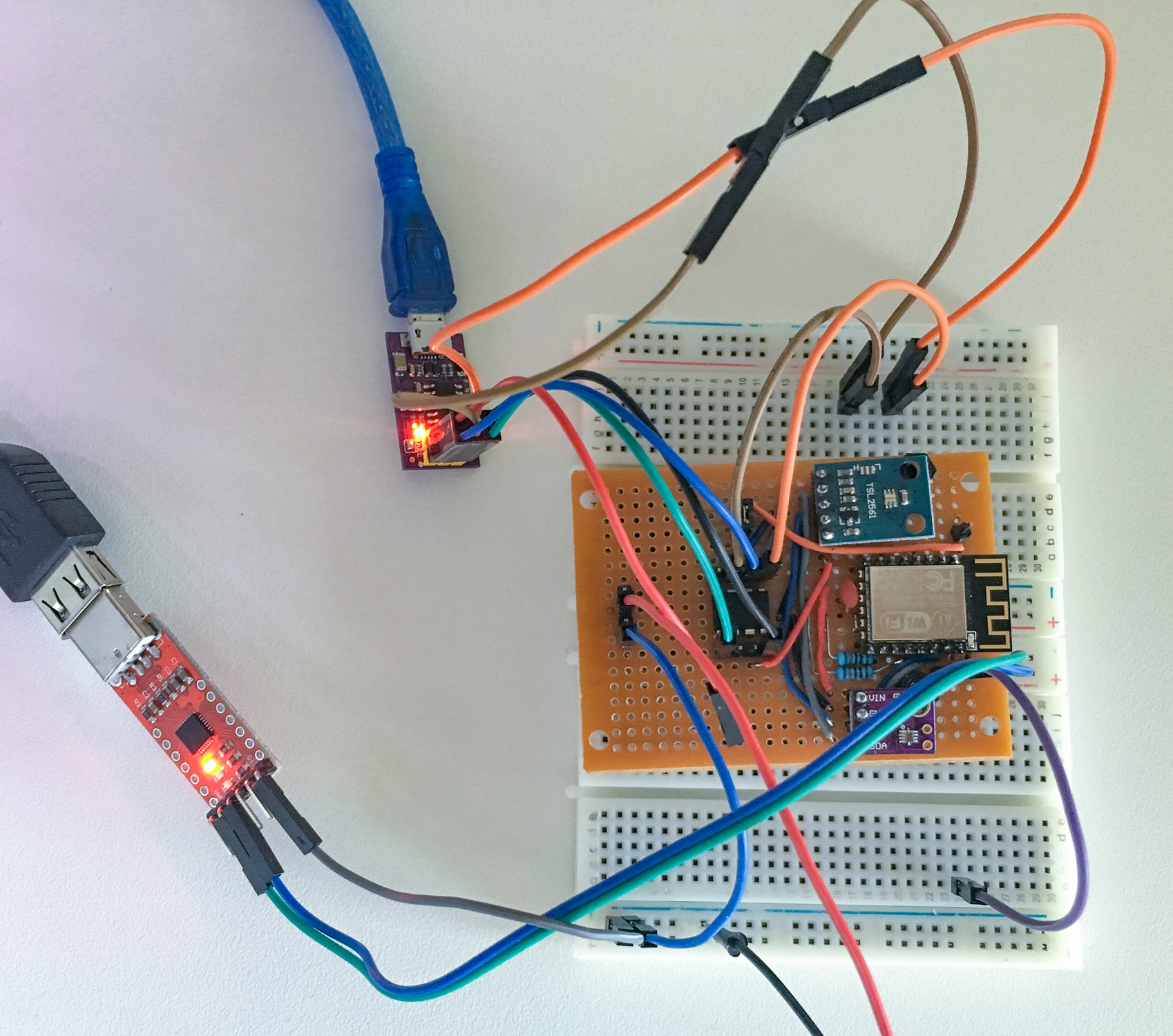
The first prototype The software was tested on a test device, assembled on a universal board and contact plate. For programming ATtiny85, the USBTinyISP clone programmer and RS232 to 3.3 V converter were used. Both elements are shown in the picture.
Projects The first idea was to keep the ESP module in deep sleep when the module is not needed for communication. After waking up, without the radio interface activated, ESP8266 consumes about 16 mA. Unfortunately, the disadvantage of this solution is the fact that after starting to connect to the network, the system needs about three seconds. That's a lot for a battery-powered system.
The author tested various solutions to shorten the time of connecting to the network, for example by assigning a static IP number. The connection time was reduced to half a second, however, sometimes - about one in ten cases - it took 1.5 seconds to connect. The author failed to investigate what is the reason - most likely it was the result of a collision in the network, because the system behaved more often during the day, and less often at night.
ATtiny85 deals with most of the tasks in the system. This microcontroller activates sensors, collects data from them via I?C, wakes up ESP8266 and uses it to send data to the server.
Calculations Before design work can go further, some power calculations need to be made. They are contained in the table below (an Excel sheet with these calculations can be downloaded from the author's website).
As can be seen from the above calculations, two AA alkaline batteries - about 2000 mAh in total - should allow the sensor to operate for four years in this optimistic scenario. Real time will be shorter; as the author estimates, about two years. This value will be confirmed experimentally.
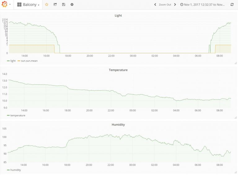
Example of system operation In the screenshot below you can see sample data presented by Grafana. They show the course of measured values in one day.
Required materials The author ordered all elements necessary for the construction of the system on AliExpress. You need:
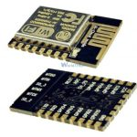
* ESP8266 12E module.
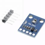
* Plate with TSL2561.
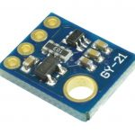
* Plate with SI7021.
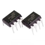
* ATtiny85 microcontroller.
In addition, you need a universal board that will allow you to connect these modules to each other.
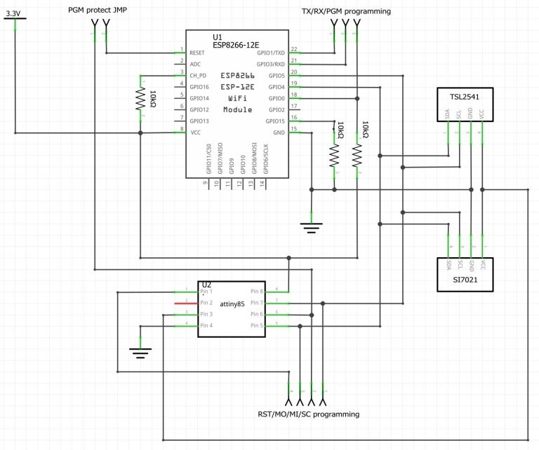
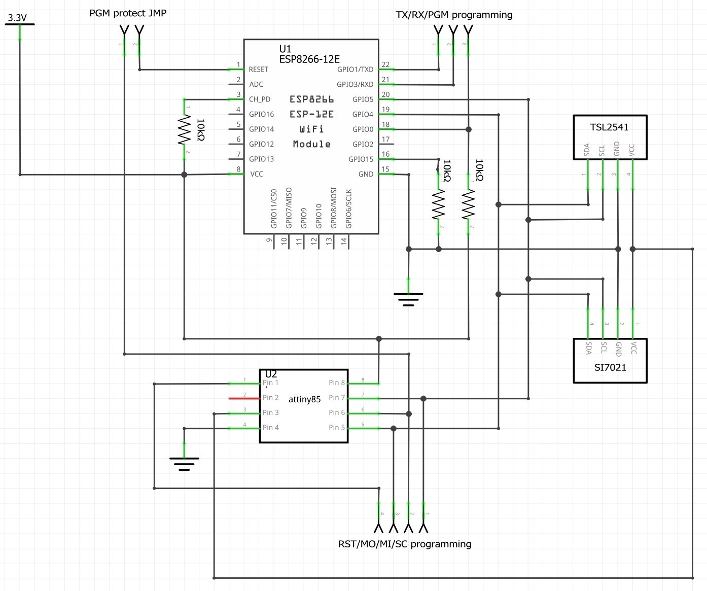
Schematic diagram The diagram below shows how individual components are connected together in the system:
The module with ESP and the ATtiny85 microcontroller are connected to the same I?C interface lines. There are no pull-up resistors on the diagram on the SCL and SDA lines, because they are on the sensor boards.
Sensors are powered via the PB4 pin in ATtiny. Thanks to this, they can be disconnected when the microcontroller is asleep - this gives additional power savings.
All measurements are remembered by the AVR microcontroller. When he wants to wake up ESP, he must download the PB1 line to ground for a few milliseconds, which causes the ESP8266 module to start.
There are two programming connectors on the board:
- one for ESP8266, which is programmed via UART. Just remove the PGM protect jumper, pull PGM to ground and connect the appropriate converter to TX and RX pins to UART 3.3 V. After programming, we stop downloading PGM to ground and put the jumper on;
- the second connector is for ATtiny programming via the SPI interface. Pins Reset, MOSI, MISO, SCK and ground are connected to the programmer, in this case TinyUSBISP.
Program work cycle 1. The ATtina microcontroller is dormant. He wakes up every second to see if he needs to take a measurement; if not, it goes back to sleep.
2. Every two minutes of deep sleep, the system turns on and energizes the sensors.
3. Through the I?C interface, the microcontroller, as a master, reads data from the sensors.
4. After completing the measurements and saving the data, ATtiny turns off the power to the sensors and goes into sleep mode.
5. Every hour (30 measurements) the microcontroller wakes up ESP8266 and configures its I?C interface to work as a slave. Waiting for ESP responses now.
6. After starting the ESP8266 microcontroller downloads data, along with some statistics from AVR through I?C.
7. ESP8266 connects to the server written in Python and sends the downloaded data.
8. After the data has been successfully transferred to the ESP8266 server, it informs ATtiny85 that the data has been successfully sent and can be safely deleted.
9. ESP8266 goes to sleep.
10. ATtiny has completed its cycle, so it goes to sleep and the above sequence starts again.
Firmware for ATtiny85 The program code, written in Arduino, can be found on GitHub of the author of the project (link at the bottom).
The main loop of the program contains a state machine controlling what the system is currently doing - sleeps, measures, wakes up ESP or sends data. When the measurement is done, it will be saved to RAM, and if it is not possible, because it will be, for example, full, the oldest record will be deleted.
Important files: [/ v]
Setup.h : Here is the main configuration of the program. The deviceID variable identifies the device exactly. It also records how often measurements are made, and how often the AVR wakes up the ESP module to send data via a Wi-Fi network.
Power.h : This file contains methods for turning sensor power on and off, waking up ESP, and putting the ESP system to sleep in deep sleep for one second.
Storage.h : This is an abstraction class that allows you to store measurements in RAM. Uses the SensorData structure, which is passed to this class. This class also has a number of methods, including data byte-by-byte, so that it can be sent via I?C.
Sensor.h : Library for sensor support: TSL2541 for measuring the brightness of the sun and SI7021 for measuring the temperature and humidity.
SlaveI2C.h : Library for ATtiny85 support in Slave mode on I?C when ESP is the master. This library is responsible for sending data from memory to ESP8266. The following commands are used during this transmission:
'B' - ESP requires system statistics. They are sent in the form of 9 bytes in AABBCCDEF format, where:
AA (uint16) is the number of measurement bytes that are ready to be sent.
BB (uint16) is the ESP wake up frequency in seconds.
CC (uint16) is the measurement frequency in seconds.
D (uint8) is the size of the SensorData structure in bytes.
E (uint8) is the device number from 0 to 9, it must be unique.
F (uint8) is the number of logical (not physical) sensors - it is needed so that the data server knows how many data fields to prepare for each measurement.
'D' - ESP requires raw measurement data, we send them byte by byte. ESP knows how many bytes it must read because this information is contained in statistics.
'A' - Data has been successfully transferred to the database on the server, you can empty the data buffer.
'Z' - ESP informs that it is going to sleep, which means that ATtiny can start the next cycle of action.
Firmware for ESP8266
The code written in Arduino for this system is also available on GitHub.
The program running on ESP is very simple. The system reads Wi-Fi network data from EEPROM and connects to the Access Point using static IP to make everything work as quickly as possible. After connecting to the wireless network, the system reads statistics from ATtina, and then downloads data from the system.
The downloaded data are sent as TCP packets to the database server.
After the transmission is finished, the system informs AVR about the success of the operation and goes to sleep.
[u] Important files: MyWifi.h : GPIO14 ESP pin is internally pulled up to the power supply, but if during startup it will be in a low state, then the system will enter the so-called WiFiManagera. In this state, ESP8266 is configured as AP and allows the user to configure the following parameters after connection:
* Static IP address
* Subnet mask,
* Gateway address,
* Remote server IP,
* The port on which the server listens for packets.
All these data are saved on the internal EEPROM, from where the system loads them each time, starting in normal operation mode.
MasterI2C.h : This library supports the I?C interface. It downloads statistics and measurement data from AVR and sends them via Wi-Fi to the server. This system does not read measurement data at all, it only passes it on.
Database Server The server application was written in Python. Server sources can also be found on the author's GitHub.
Server operation is very simple. It simply listens for TCP communication on a specific port. When a packet gets there, the program starts a new thread that handles the received data. The data packets are parsed and then thrown into the InfluxDB database, along with the name and time (timestamp) for later processing, analysis or presentation.
Important files main.py : Here is the configuration on which TCP port the server should listen. This is also where you can log in to the server with the InfluxDB database.
The program first connects to the database, then a separate parser is started for each device identified by deviceID, because each device may have differently configured sensors or times between measurements. In addition, thanks to this the application works better in a multi-threaded system. The TCP server is finally started, which starts listening and receiving incoming packets.
influx.py : When the class saved in this file is declared, a connection to the InfluxDB database is established. This class has a writeData method, which is used to save measurements in the database. This method is used by the sensorParser class.
server.py : Connects to the TCP port and listens in an endless loop. After receiving the package, relying on deviceID, it launches the appropriate sensorParser object and passes the data to it.
generalParser.py : This is a general parser for incoming data. It breaks down the package into individual parts and analyzes data such as:
* Device ID,
* Time between ATtina measurements,
* How often ESP wakes up,
* How many sensors are in the system.
Then it begins to analyze the measurement data and passes it to the overloaded handleNexMeasurement method. This method, in turn, uses simple helper methods - getFloat, getUint, and getByte to interpret data.
sensorParse.py : The main purpose of this file is to overload the handleNextMeasurement method in generalParser.py. This method includes all the details of the data analysis for each deviceID, so it is here that names are assigned to measurements before they are entered into the database. The contents of this file should be edited if we want to change the set of sensors in the system.
Measurements of real power consumption ESP8266 is really a very energy intensive system. Therefore, it is worth checking how much real power this system absorbs when it transmits data packets. For this purpose, the author used his logger to measure current and voltage. The results are presented in the following chart:
ESP is awakened for about 0.7 s and then consumes an average of 78 mA.
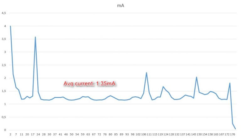
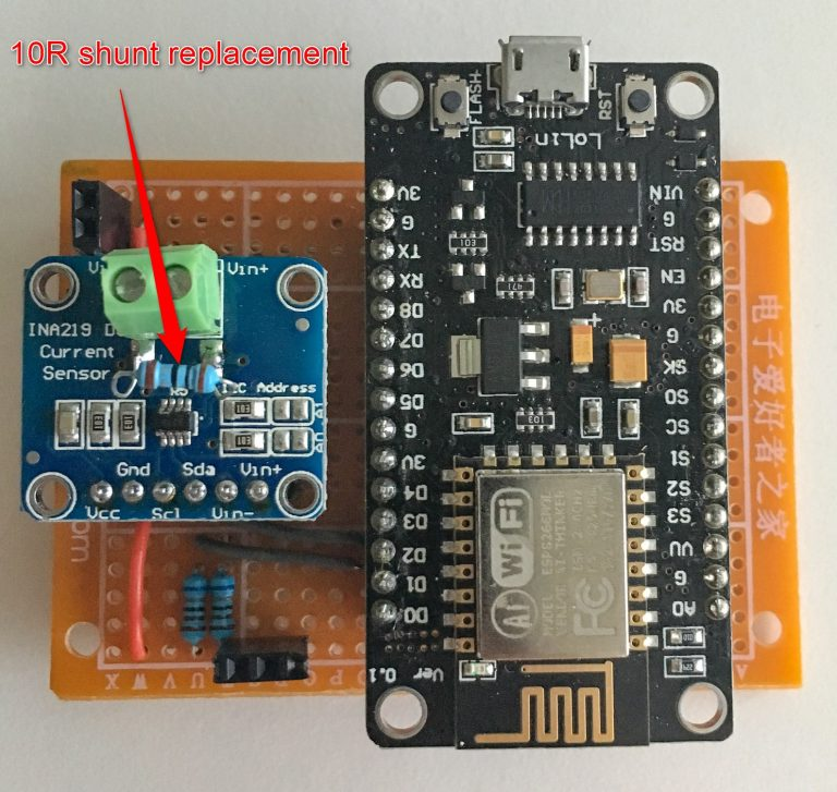
Another is the measurement of current consumption by ATtiny during the measurements. This current is so small that it was necessary to change the measuring resistor shorted in INA219 from 0.1 ? to 10 ?, i.e. increase the sensitivity (transconductance) of the system by a hundred times.
The measurement shows that the system collects data for approximately 180 ms and consumes an average of 1.35 mA during this time. The power consumption is so low due to the reduction of the system clock from 8 MHz to 1 MHz. At a higher frequency, the consumption was over 10 mA.
Modifications introduced to the current measurement system:
During sleep the system consumes about 23.5 uA - the whole system: ESP and ATtiny. This is electricity straight from the battery, without a DC / DC converter, which could further reduce the current drawn from the cells.
After collecting all the above measurements, it was possible to sum up the current consumption and estimate how long the battery in the system should be enough. The calculations are shown in the table below. It turns out that they are quite similar to the initial ones.
Further plans The next step of the author of the design is to install a DC / DC converter in the system, which is to help further increase the energy efficiency of the system.
Sources:
https://github.com/x821938/UltraLowPower_WeatherStation https://www.cron.dk/esp8266-on-batteries-for-years-part-1/ https://www.cron.dk/esp8266-on-batteries-for-years-part-2/ https://www.cron.dk/esp8266-on-batteries-for-years-part-3/ https://www.cron.dk/esp8266-on-batteries-for-years-part-4/ https://www.cron.dk/esp8266-on-batteries-for-years-part-5/


Comments
So why did the author use an additional processor? There is no mention that after using ATtiny85 ESP connects to the network faster. In my opinion, such a powerful processor as ESP8266 calmly cope with... [Read more]
Please note that this is a translation of a foreign website. There is no point in arguing with this text. You are curious - write to the author. He doesn't read this forum. [Read more]
Maybe the point is that a converter will be used, allowing "to pull" the maximum from the battery when it is too weak (voltage drops during operation) to ensure normal operation of the system? A simple... [Read more]
Looking at the ESP plate, it's more about using a step-down converter instead of a linear stabilizer. There are such with very low current Iq and then we would actually observe a decrease in current.... [Read more]
Similar results can be obtained on ESP8266 itself, waking it every 2 minutes (mentioned in the original article) and wifi only firing every hour. In this way, the working current will be larger, but the... [Read more]
I just wrote about it more than once. ESP doesn't cope with its accespoint at all. The program freezes then and ESP drains the battery until the mains power or end of power supply. I just don't... [Read more]
In my opinion, it is the fault of libraries that do not implement timeout functionality and do not allow the parallel operation of two threads - wifi transmission has a high priority, but a simple user... [Read more]
I am also looking for a solution for measuring temperature and sending data via ESP on battery power. I think ESP8266 and Attiny (low voltage series) are the perfect combination. I do not understand, however,... [Read more]
But how not to hang like most programs / examples uses the while function // Wait for connection while ( WiFi.status() != WL_CONNECTED ) { delay ( 500 ); Serial.print ( "." ); } In my... [Read more]
In my opinion, such a powerful processor as ESP8266 calmly cope with all tasks without Attina. First of all, it will consume several times more energy, it will discharge the battery faster. Secondly,... [Read more]
No ESP has ever crashed during work or when connecting to the network. I check if the connection doesn't take too long and if so esp.reset (); int rtr=0; while ( WiFi.status()... [Read more]