In the material below, the author describes how to use Arduino and an RFID reader to build a simple lock. In this system, Arduino reads the RFID tag ID with the help of a special reader. The identifier is displayed on the OLED screen, and if it matches the number stored in the system's memory, it displays the word "Unlocked", it can also open the lock etc.
Step 1: Required items The following modules are needed to compile the following system:
* Arduino Uno module
* RFID tag reader
* OLED screen
* Small universal plate
* Some cables to make connections.
In addition, we will need a power supply or power bank that will enable powering the Arduino module.
The cost of setting up the system is about $ 15.
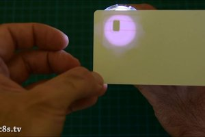
Step 2: RF5 Reader RF522 Each RFID tag contains a small integrated circuit. If we put it in the light of a flashlight, we will see inside a small integrated circuit and a coil - an antenna - around it. This module has no batteries. It draws energy to supply from the surroundings, through the antenna. When we place it next to the reader, the radio waves of the reader induce current in the coil, which is enough for the RFID module to send information in response. The maximum distance between the reader and the tag is about 20 mm.
The same integrated circuits and antennas as shown above can also be found in RFID cards, keyrings or in some equipment.
Each RFID has its own unique identification number - UID. This number is displayed on the OLED system display. In addition to the UID itself, we can save some data in the system - up to 1 Kb of data. In this system we will not use this option, but the author plans to create another tutorial, in which it will be described.
In this article we will focus on identifying a specific tag through its UID. Based on this number, we will open the lock.
The described technology is widely used and very cheap. The cost of an RFID reader and two tags is about $ 4.
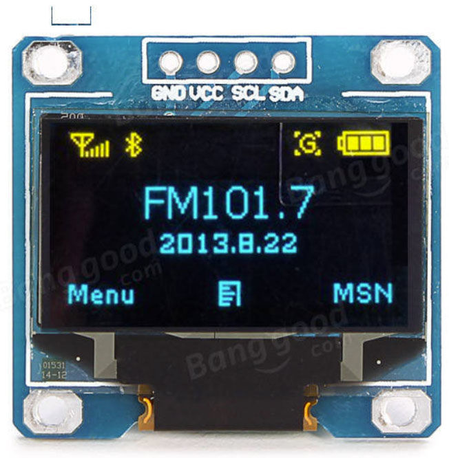
Step 3: OLED display OLED displays are readily used in projects with Arduino, due to low power consumption and excellent screen readability. The current consumption of a typical display of this type is about 10..20 mA and depends on how many pixels are lit.
The display used has a resolution of 128 x 64. These miniature displays are available in two versions - monochrome or divided into two sections - blue and yellow.
In addition to the advantages mentioned above, OLED displays are also easy to control. They are controlled by the I?C interface, thanks to which, apart from power supply, it is enough to connect two leads of the microcontroller to them. In addition, ready-made, easy-to-use libraries dedicated to this type of display are available for Arduino. A wider description of using this library can be found in the following video:
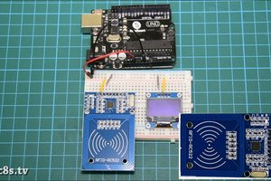
Step 4: Connection of individual elements Connecting individual elements to the Arduino module is very simple. We must connect the display and RFID reader to the module with the microcontroller. It is important that the reader is connected to a 3.3 V and not 5 V power supply (can work with both), otherwise it will damage the Arduino. Therefore, we connect the reader and display Vcc to a 3.3 V power supply. We should also remember to connect the ground pins together.
OLED display - Arduino
Vcc ? 3.3V
GND ? GND
SCL ? Analog pin number 5
SDA ? Analog pin number 4
RFID reader - Arduino
RST ? Digital pin number 9
IRQ ? Not connected
MISO ? Digital pin number 12
MOSI ? Digital pin number 11
SCK ? Digital pin number 13
SDA ? Digital pin number 10
The RFID module uses the SPI interface for communication. Therefore, we will use the SPI hardware module in the Arduino UNO module. The OLED module, as we wrote above, uses the I?C interface, which is why we connect it to pins 4 and 5, where we will find the hardware I?C module.
Now just connect the system to the power supply and upload the appropriate program to Arduino to make everything work.
Step 5: Software The software for our system is written in the Arduino IDE. To make this possible, we need to install the appropriate libraries. Click on Sketch -> Include Libraries -> Manage libraries and look for the library for the MFRC522 module and install it. Then, in the same way, install the display library - SSD1306 - and the Adafruit GFX library. The library that supports the display requires a few minor changes. Click on the Arduino / Libraries folder and open the folder with Adafruit SSD1306, where we edit the Adafruit_SSD1306.h file. In the library, we must comment on line 70 and uncomment line 69, which will allow the library to be adapted to 128x64 resolution.
Now let's look at the program code itself.
First, we must declare the UID value of the RFID tag, which is to be recognized by the program. It is an integer matrix (int):
Then we initialize the RFID reader and display:
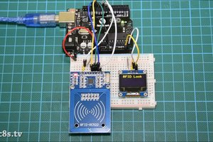
Then the program starts the main program loop in which it reads the value of the reader through the SPI every 100 ms. If the value read is the same as that written in the variable defined at the beginning, the program executes the code contained in the appropriate place of the if function:
In this case, it is displaying information about the card recognition and 'opening the lock', i.e. displaying such an inscription. In our system there may be anything else, e.g. control of a servomotor or a motor controlling a real lock.
The full Arduino sketch code is below:
[syntax=c] /////////////////////////////////////////////////////////////////
// Arduino RFID Tutorial v1.02 //
// Get the latest version of the code here: //
//
http://educ8s.tv/arduino-rfid-tutorial/ //
/////////////////////////////////////////////////////////////////
#include
#include
#include
#include
#define OLED_RESET 4
Adafruit_SSD1306 display(OLED_RESET);
#define SS_PIN 10
#define RST_PIN 9
MFRC522 rfid(SS_PIN, RST_PIN); // Instance of the class
MFRC522::MIFARE_Key key;
int code[] = {69,141,8,136}; //This is the stored UID
int codeRead = 0;
String uidString;
void setup() {
Serial.begin(9600);
SPI.begin(); // Init SPI bus
rfid.PCD_Init(); // Init MFRC522
display.begin(SSD1306_SWITCHCAPVCC, 0x3C); // initialize with the I2C addr 0x3D (for the 128x64)
// Clear the buffer.
display.clearDisplay();
display.display();
display.setTextColor(WHITE); // or BLACK);
display.setTextSize(2);
display.setCursor(10,0);
display.print("RFID Lock");
display.display();
}
void loop() {
if( rfid.PICC_IsNewCardPresent())
{
readRFID();
}
delay(100);
}
void readRFID()
{
rfid.PICC_ReadCardSerial();
Serial.print(F("\nPICC type: "));
MFRC522::PICC_Type piccType = rfid.PICC_GetType(rfid.uid.sak);
Serial.println(rfid.PICC_GetTypeName(piccType));
// Check is the PICC of Classic MIFARE type
if (piccType != MFRC522::PICC_TYPE_MIFARE_MINI &&
piccType != MFRC522::PICC_TYPE_MIFARE_1K &&
piccType != MFRC522::PICC_TYPE_MIFARE_4K) {
Serial.println(F("Your tag is not of type MIFARE Classic."));
return;
}
clearUID();
Serial.println("Scanned PICC's UID:");
printDec(rfid.uid.uidByte, rfid.uid.size);
uidString = String(rfid.uid.uidByte[0])+" "+String(rfid.uid.uidByte[1])+" "+String(rfid.uid.uidByte[2])+ " "+String(rfid.uid.uidByte[3]);
printUID();
int i = 0;
boolean match = true;
while(i


Comments
"The maximum distance between the reader and the tag is about 20 mm." After changing the antenna matching calmly 100mm ... On the MFRC522 you can easily run DESFire EVx or other such type tw ISO14443-4... [Read more]
What type of electronic lock for the front door does it matter? [Read more]
@eXcLiFe What is the matching / RF balun on these PCBs? Good fit i.e. those from the manufacturer's datasheet? I am asking because I ordered art from my friend [Read more]
Match it with datasheet. Just replace L1 L2 with 520nH (wire) C4 C5 220pF, C10 C11 180pF. C8 C9 at 15pF. All C0G capacitors. A friend made a match for me, I don't remember if it's such values [Read more]
you can buy rfid controller assy with 20 euro from aliexpress.... [Read more]
and where to connect the lock or diode to control the state [Read more]
If the lock is unlocked and "Unlocked" is displayed, how can I make it so that "Blocked" is displayed when the lock is locked? [Read more]
And do you have access to the program? [Read more]
Not yet [Read more]
This is how Unlocked is displayed for you now [Read more]
So far I've read that it should [Read more]
It depends on what program you have, what set you have and what you use, you didn't write [Read more]
(For that matter) I use Arduino Uno rev3 display (OLED) only white https://botland.com.pl/wyswietlacze-oled/8867-wyswietlacz-oled-blu-graficzny-13-128x64px-i2c-v2-biale-znaki-sh1106-5903351241182.html ... [Read more]
Nio has a lot of RFID software [Read more]
It will probably be as written by the author only with this modification (unless it is) ///////////////////////////////////////////////////////////////// // Arduino RFID Tutorial v1.02 // // Get the latest... [Read more]
https://www.electronics-lab.com/project/rfid-rc522-arduino-uno-oled-display/ It works, I used it myself, you can change the unlock and lock in the program from English to Polish Added after 4 [minutes]:... [Read more]