The inspiration for today's article was a colleague
@kkknc who in the thread dedicated to
gadgets that may appear in the Electrode shop , he proposed two interesting devices, and I quote:
"Cheap and interesting. 1Hz-150KHz 3.3V-30V PWM Board Pulse Signal Generator Module PWM Frequency Cycle Operation adjustable Module LCD Display https://s.click.aliexpress.com/e/uPlEreh And the second suggestion. 4-20mA Signal Generator Load Current Transducer Tester PLC Instrument LCD Two Wire Output https://s.click.aliexpress.com/e/c2UH8aa9 "
@Gulson I liked the idea, and I quote:
"Thanks, I make a note to be checked by @CMS. That's what you need here, 50 points for you" and ordered one piece for testing.
Let's move on to the presentation of the described gadget. At the beginning, a standard photo from the auction:

As you can see, it costs a lot, about twenty three zlotys, but you should add seven zlotys for shipping.
If they all have repeatable parameters and hold them like my copy, I can already say that if this gadget goes to the store, it will come off like hot cakes.
I admit that after unpacking the new toy, I didn't really know how to play with it. In the description of the auction there is information that the set includes a user manual (which, unfortunately, I did not receive), and the picture shows that a resistor is needed.
The device has only two "pins" on the rear panel and that would be enough for the connection.
After a quick consultation with a colleague
@Bestler , I found out how to bite it and after a while I was enjoying the new, very useful toy.
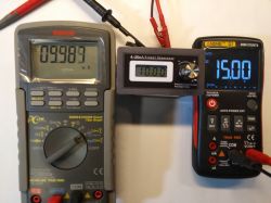
I hope that with this device, I will take you another reason for whining when testing multimeters. The device works in a very simple way, you just need to connect the power supply from 15V to 30V and that's it (although the correct indications in my unit started only at 17V).
For safety, I connected through a 470? resistor. Now it is enough to connect the device that we want to test in series with the power supply, for example a multimeter in the mile-Amp range.
The device can also be successfully used in several other ways.
- as a constant source of current signal with the possibility of adjustment and precise setting (with an accurate reading of what we have set). For example, as an offset for another signal,
- for temporary simulation of sensors with current output, e.g. replacing the sensor at the time of its failure,
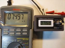
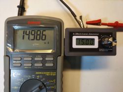
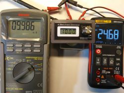
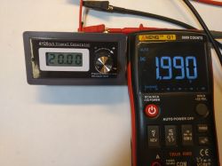
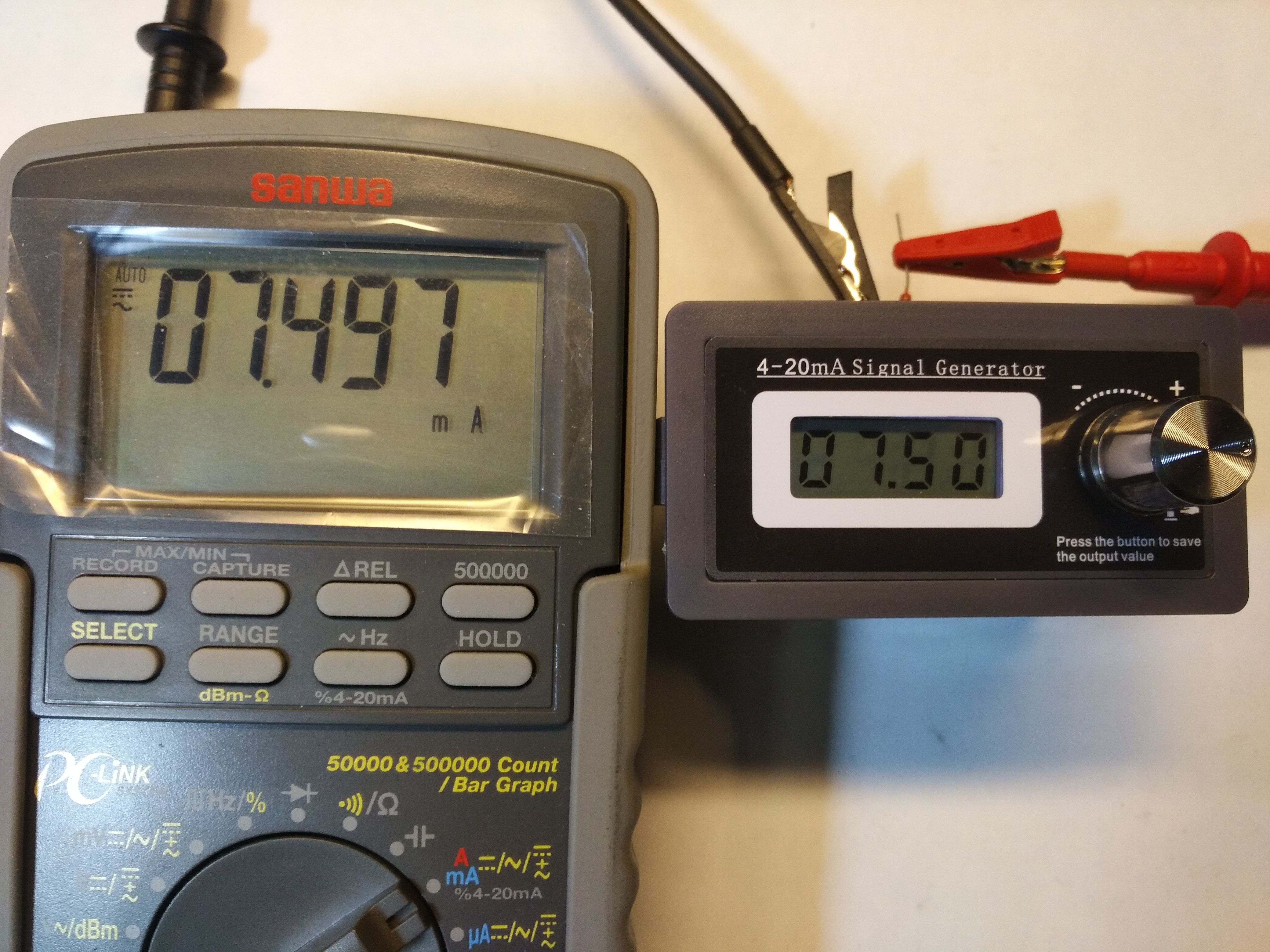
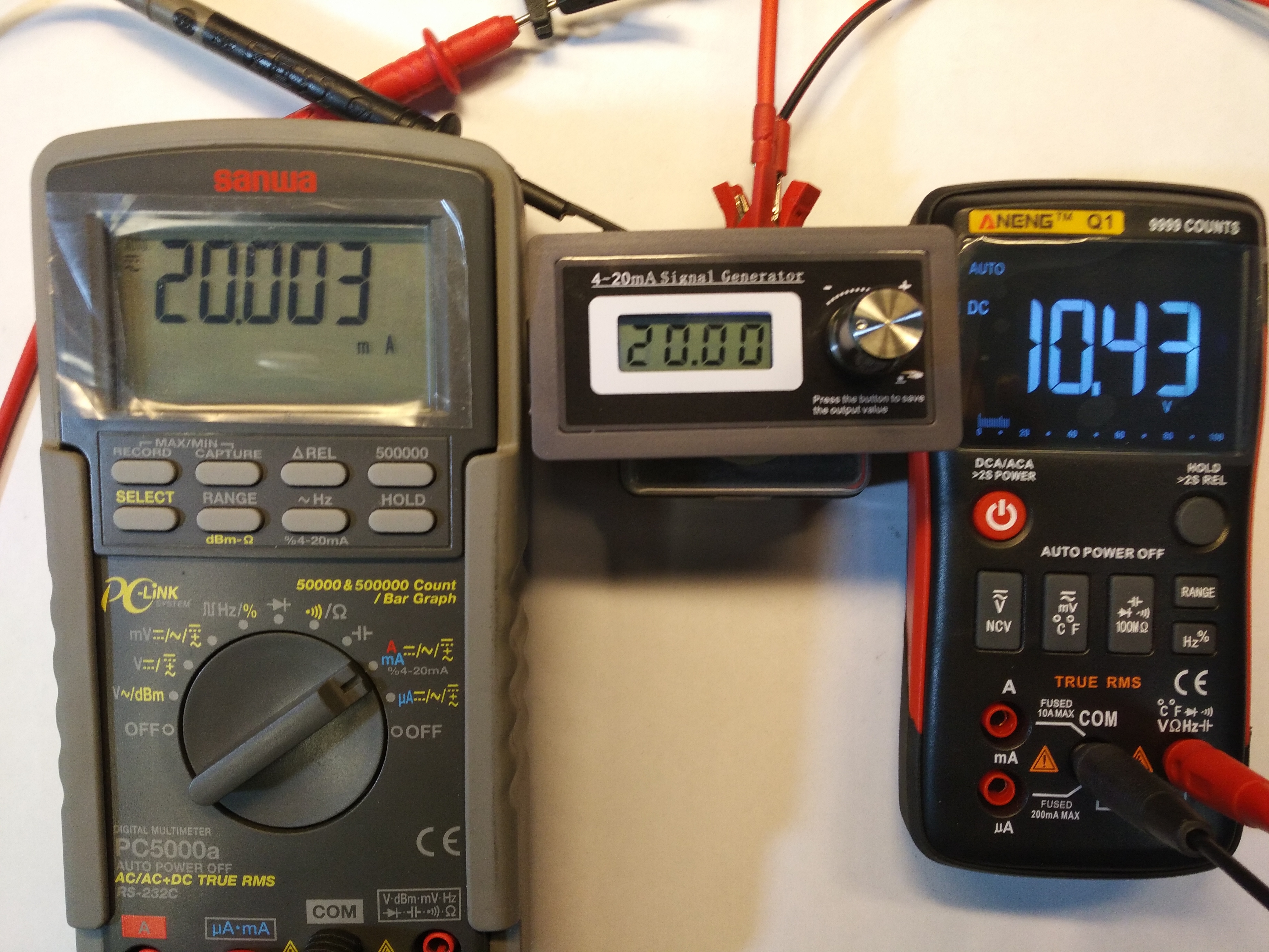
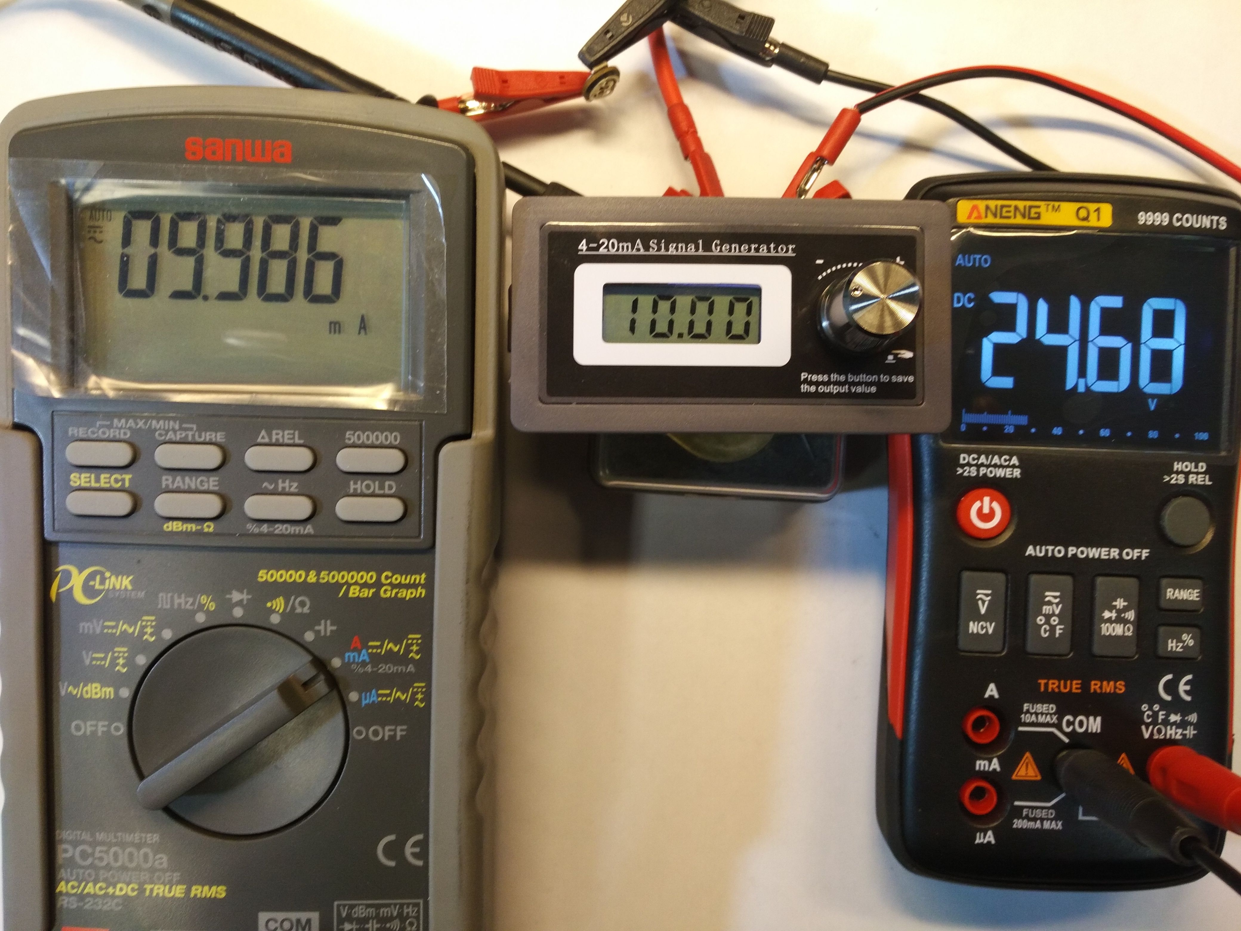
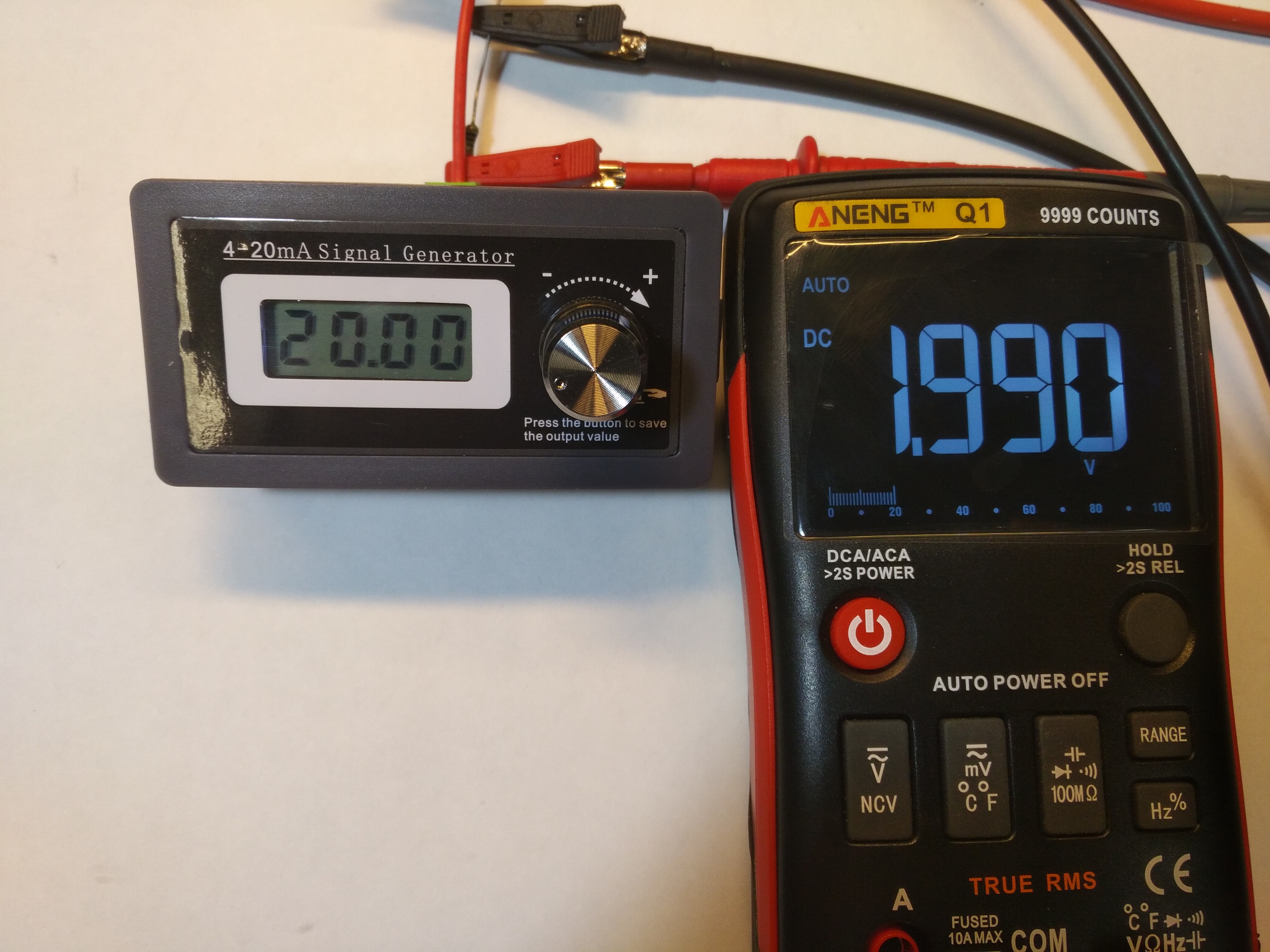
- bearing in mind the accuracy of the displayed current to two decimal places and compliance with the actual state - as can be seen in the attached photos - we can use the tested set-point as a current source to calibrate analog inputs in all devices that have a current input.
Unfortunately, despite two decimal places, the settings are not every 0.01, but every 0.05
I must admit that I was very positively surprised by the results of the measurements. The test was performed with a Sanwa multimeter, which you have already seen while reviewing the reference voltage. So you know that there is a fairly accurate device, with a slightly higher than average shelf.
Okay, I won't keep you in suspense anymore, you finally have the photographic material you want, because one image will convey more than a thousand words :)


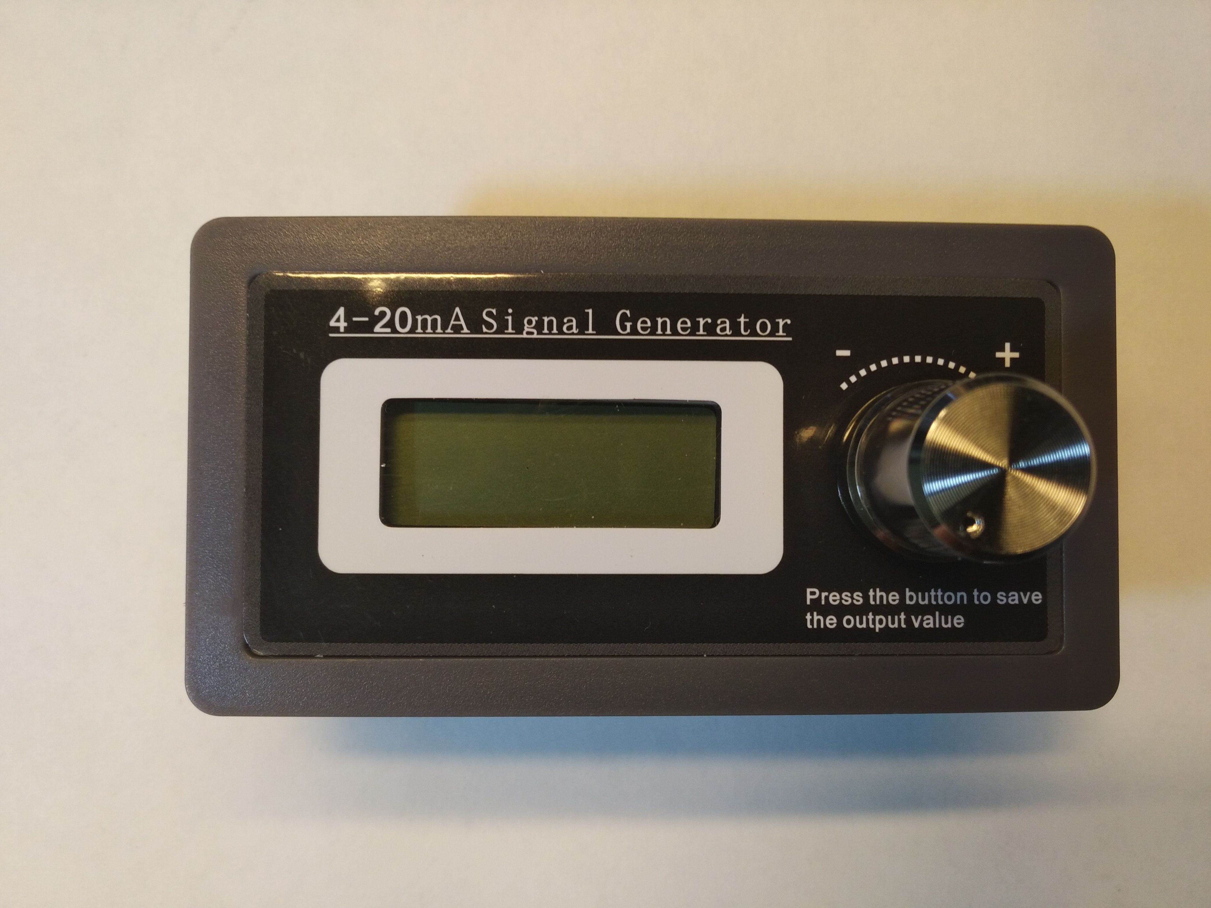
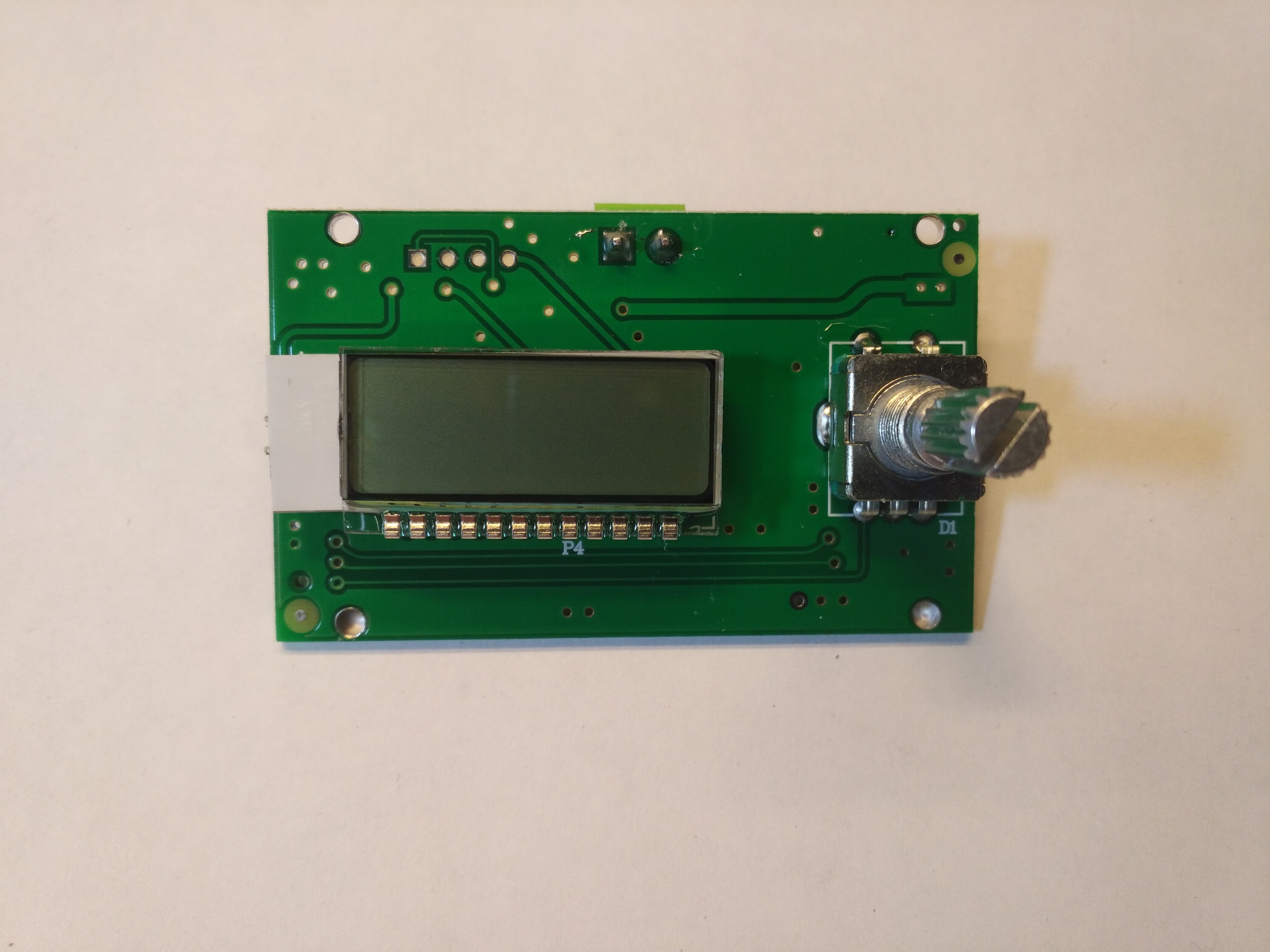
This is how this gadget looks like. The panel casing begs to be mounted as an accessory, for example in a laboratory power supply.
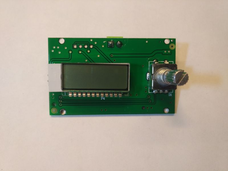
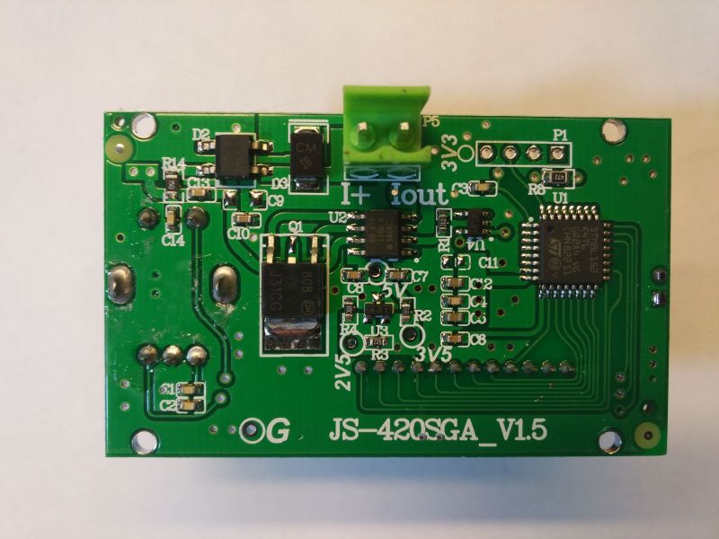
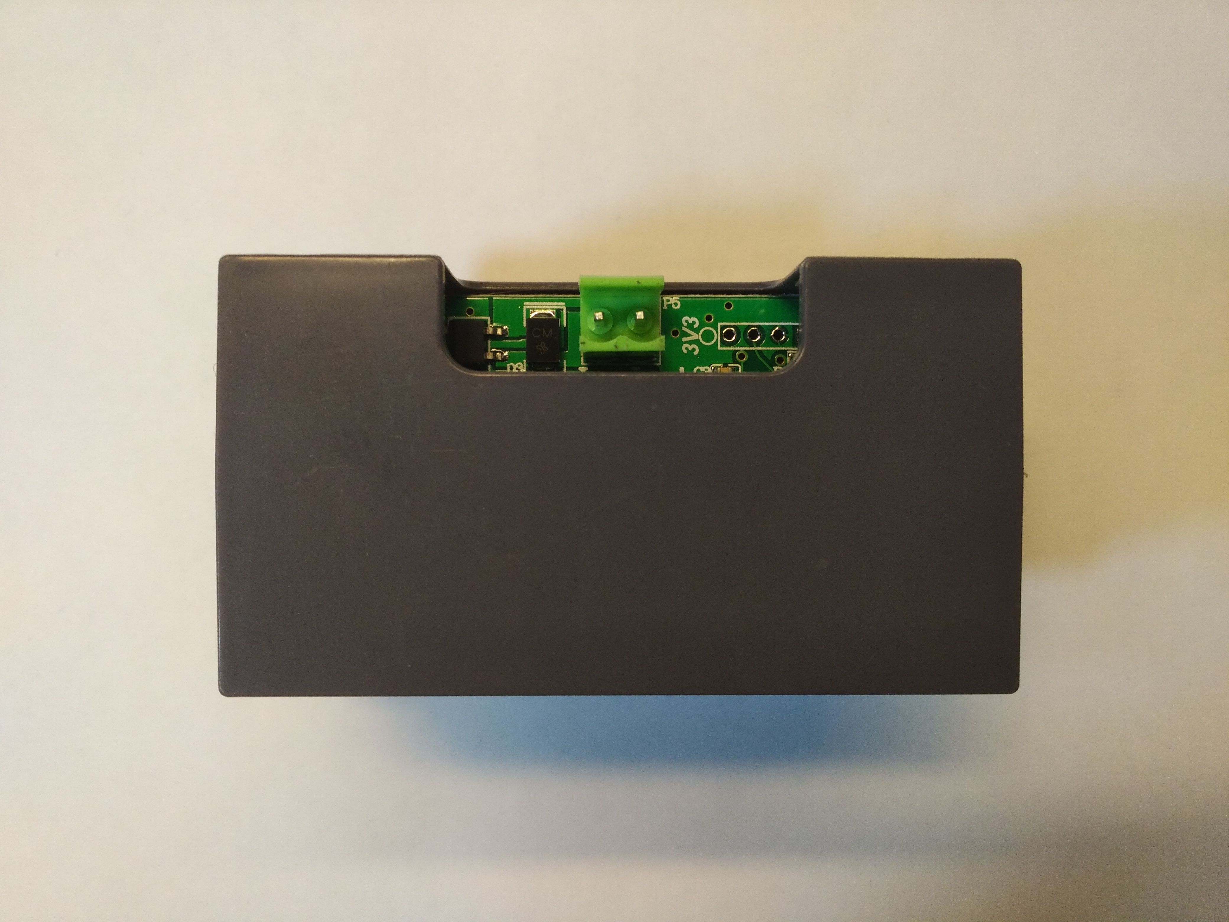
We won't find many elements inside.
Well, we finally got to the tests, you have to admit that for a gadget for thirty zlotys, there is nothing to complain about.

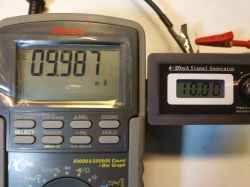
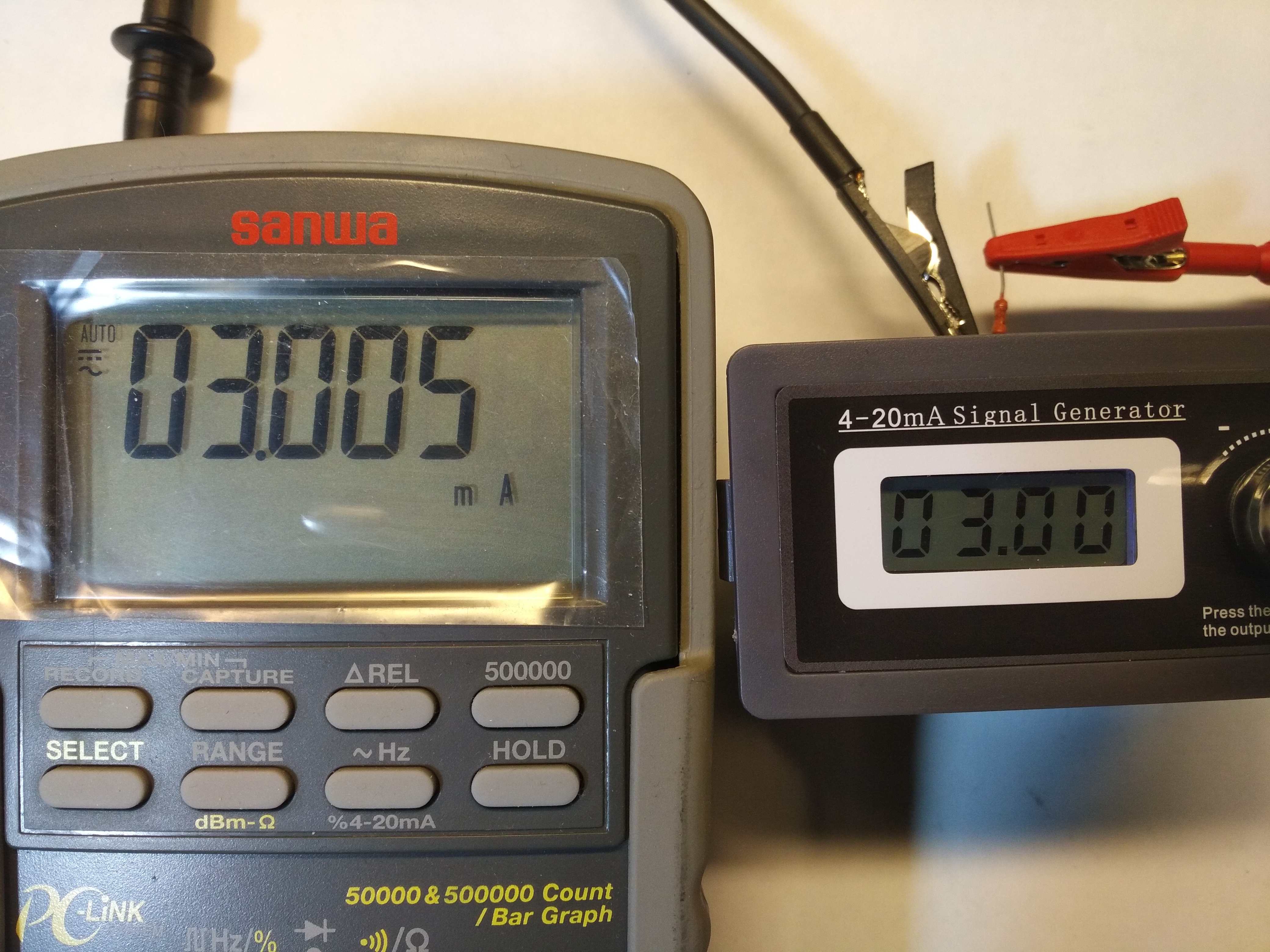
I also decided to check what the lowest and highest current I can set.

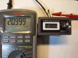
Well, applause for the producer again.
I can only fault one thing. The display has a backlight.
Seriously, it's turned on in all photos (because there is no other option), and yet it is not visible. And it's not the fault of the camera, lighting, or my other mistakes. It is barely "going". Here's a photo where I blocked most of the light from the outside with my hand:
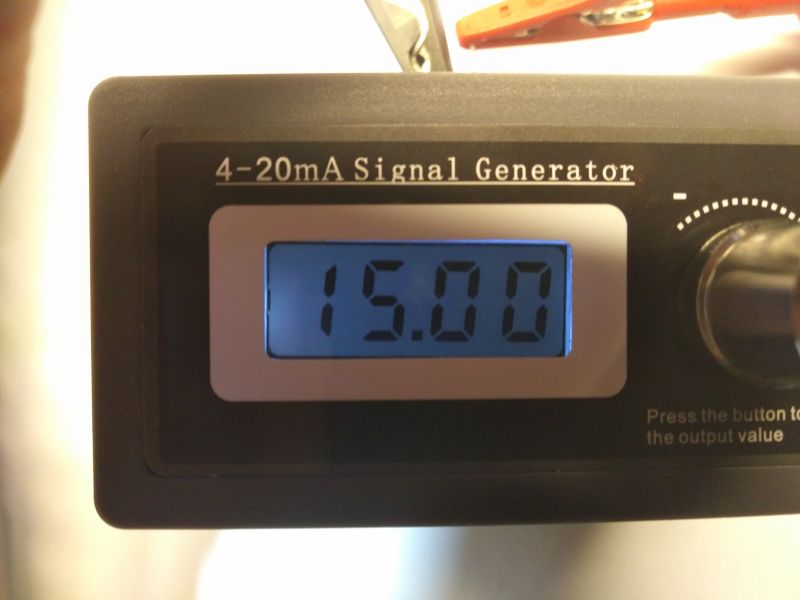
However, it does not bother you at all, because the display in daylight is very readable, and when there is no light, it can be read anyway, even with such a weak backlight.
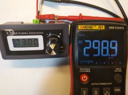
However, it should be remembered that the whole thing with the minimum setting is to consume no more than 4mA, and as you can see, even 3mA is possible. With such a weak power supply, the manufacturer should be congratulated on the fact that, despite everything, somehow managed to illuminate this display.
Summarizing: I am very happy with this gadget, the current given is very accurate and the price of the device is ridiculous. I think that this toy will permanently appear in my articles about all kinds of multimeters. Regular readers of my scribble know that I am trying to objectively evaluate the tested gadgets and, unfortunately, I am often forced to write that it is rubbish. This time, however, there is a case when I simply can't help myself and I just have to recommend you to buy this device, because it does the job so nice.
You don't even know how much my morale has just increased ... Any day you will finally get the long-promised reviews of Q1 and Clamp ...
Just as I thought the article was ready, a lively backstage discussion kicked off and thanks to that I did two more tests suggested by
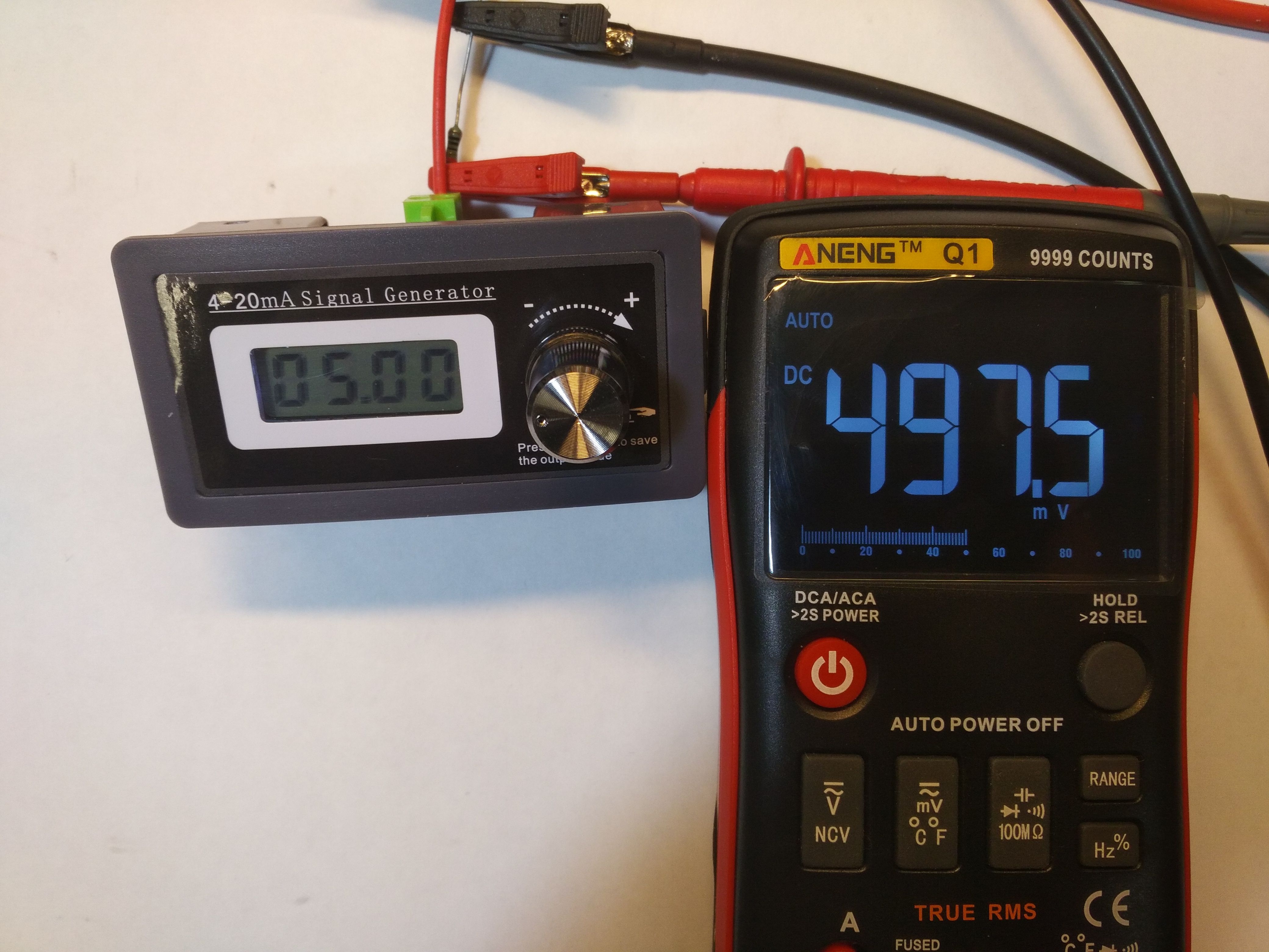
@Bestler By the way, it turned out that the problem with proper operation with power supply below 17V resulted from the use of a 470? resistor.

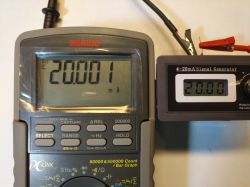
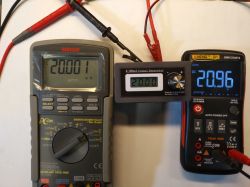
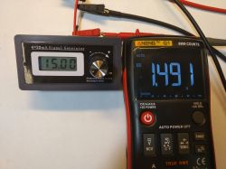
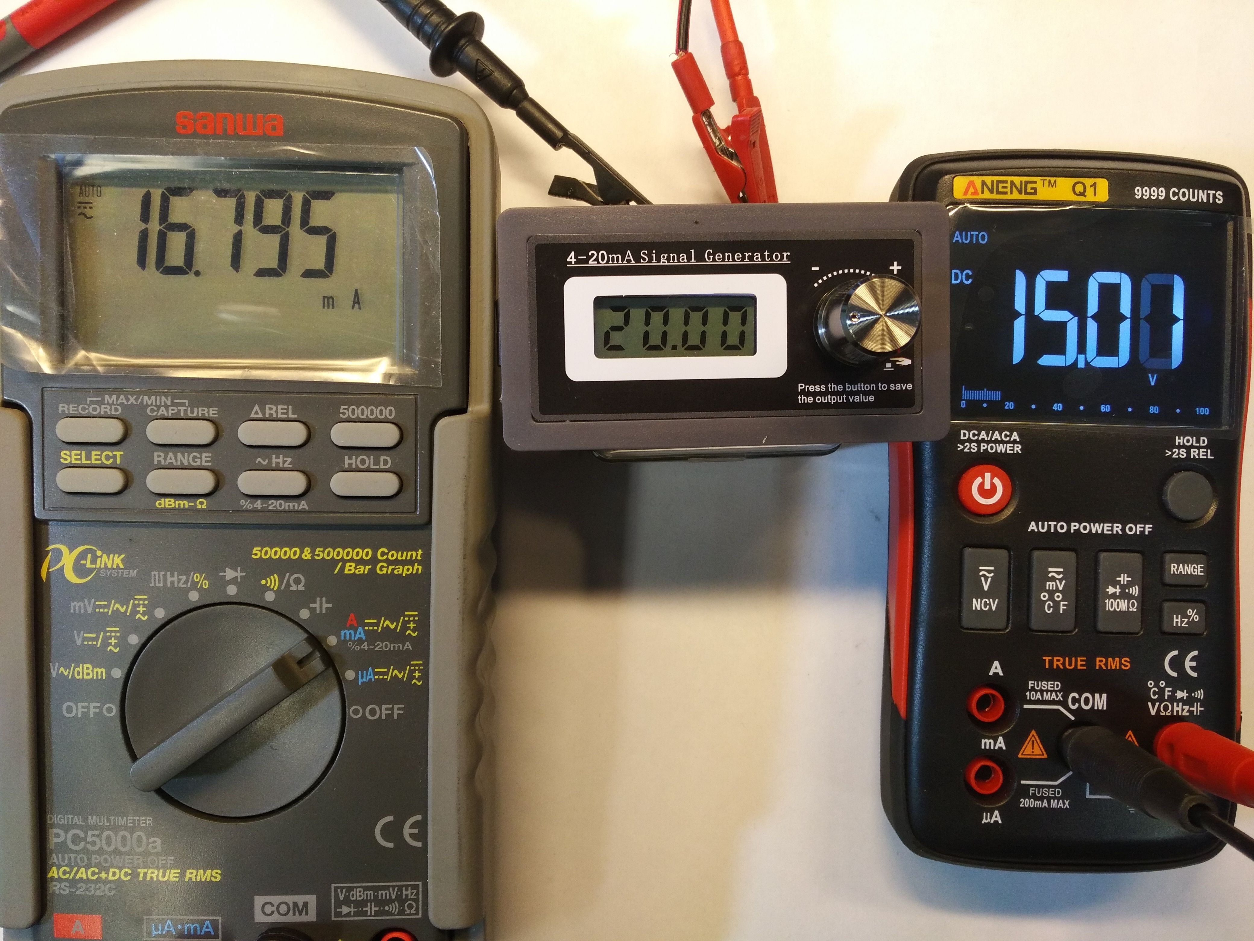
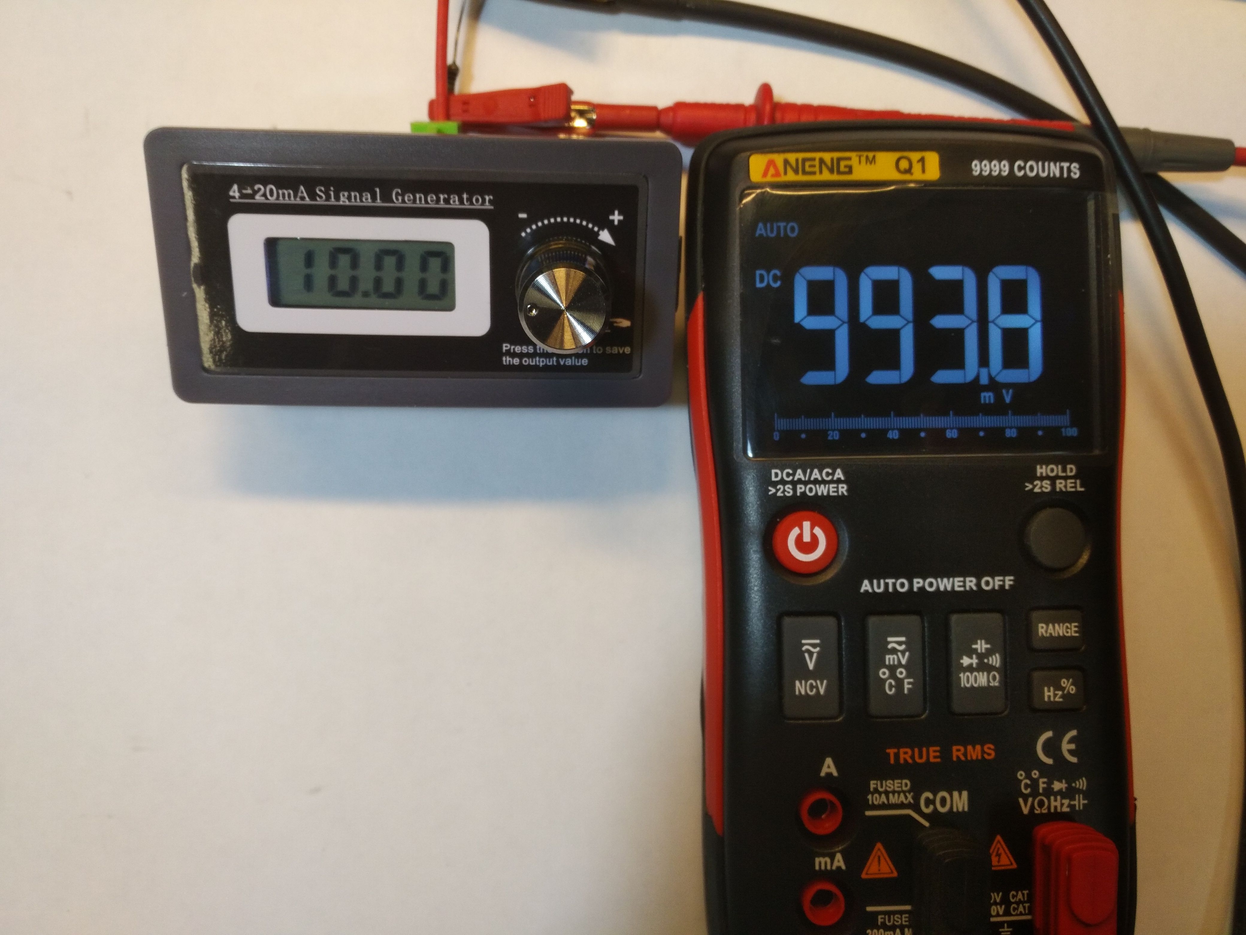
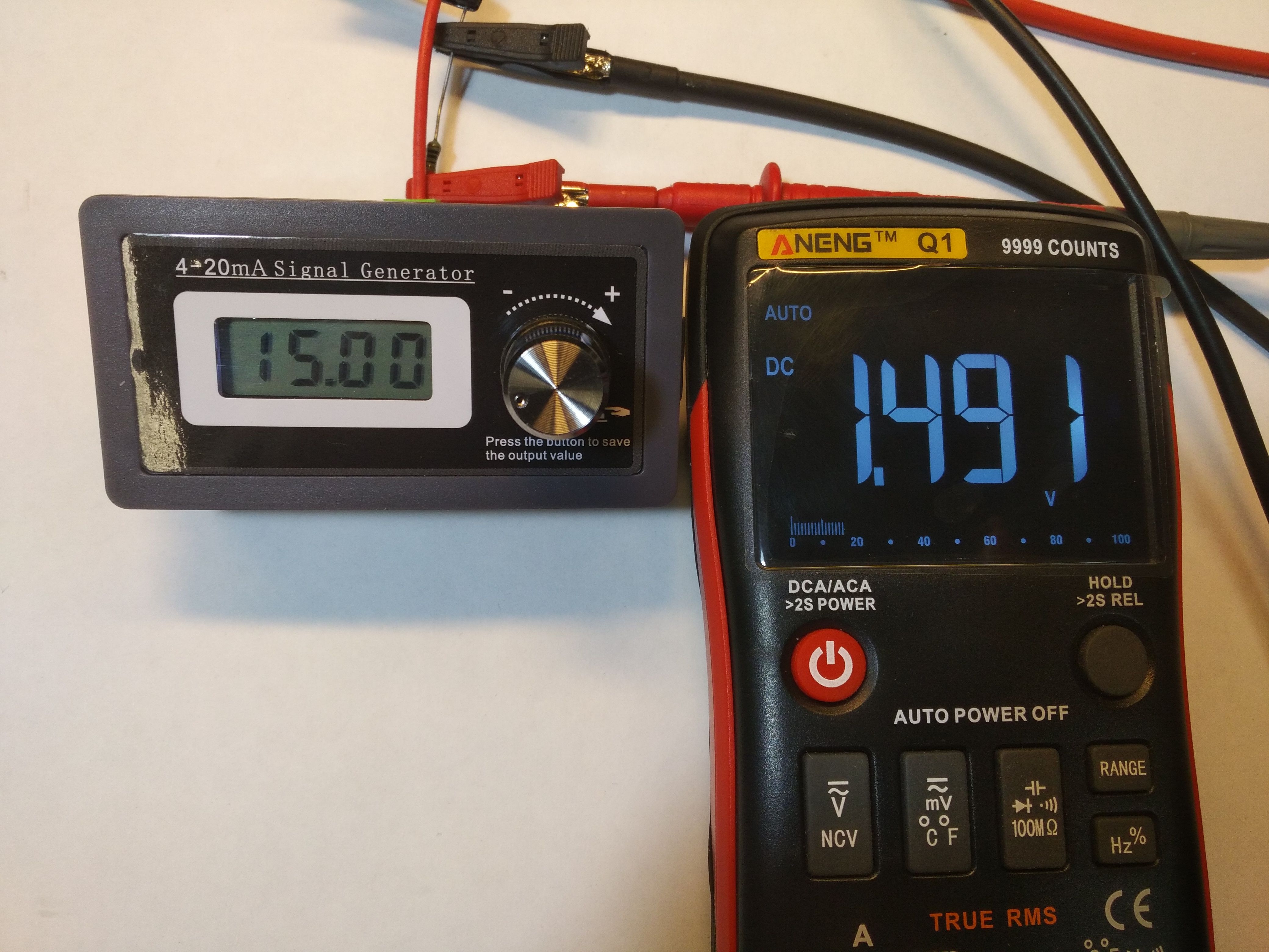
Powering 15V through a resistor, as you can see 10mA is fine, but at 20mA we already have a big error.
The correct result was obtained only at 20V:
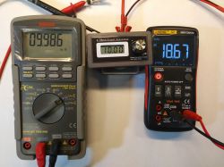
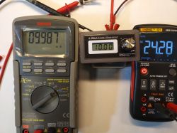
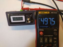
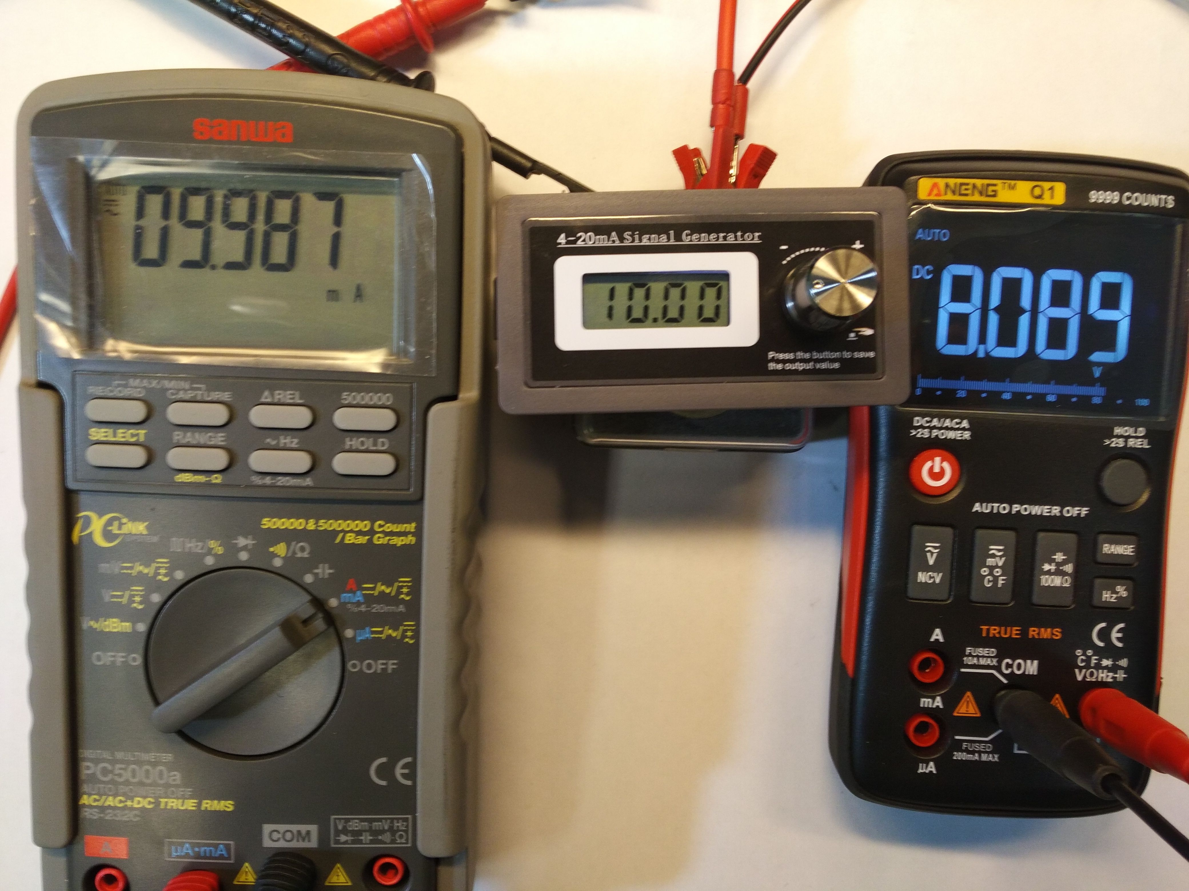
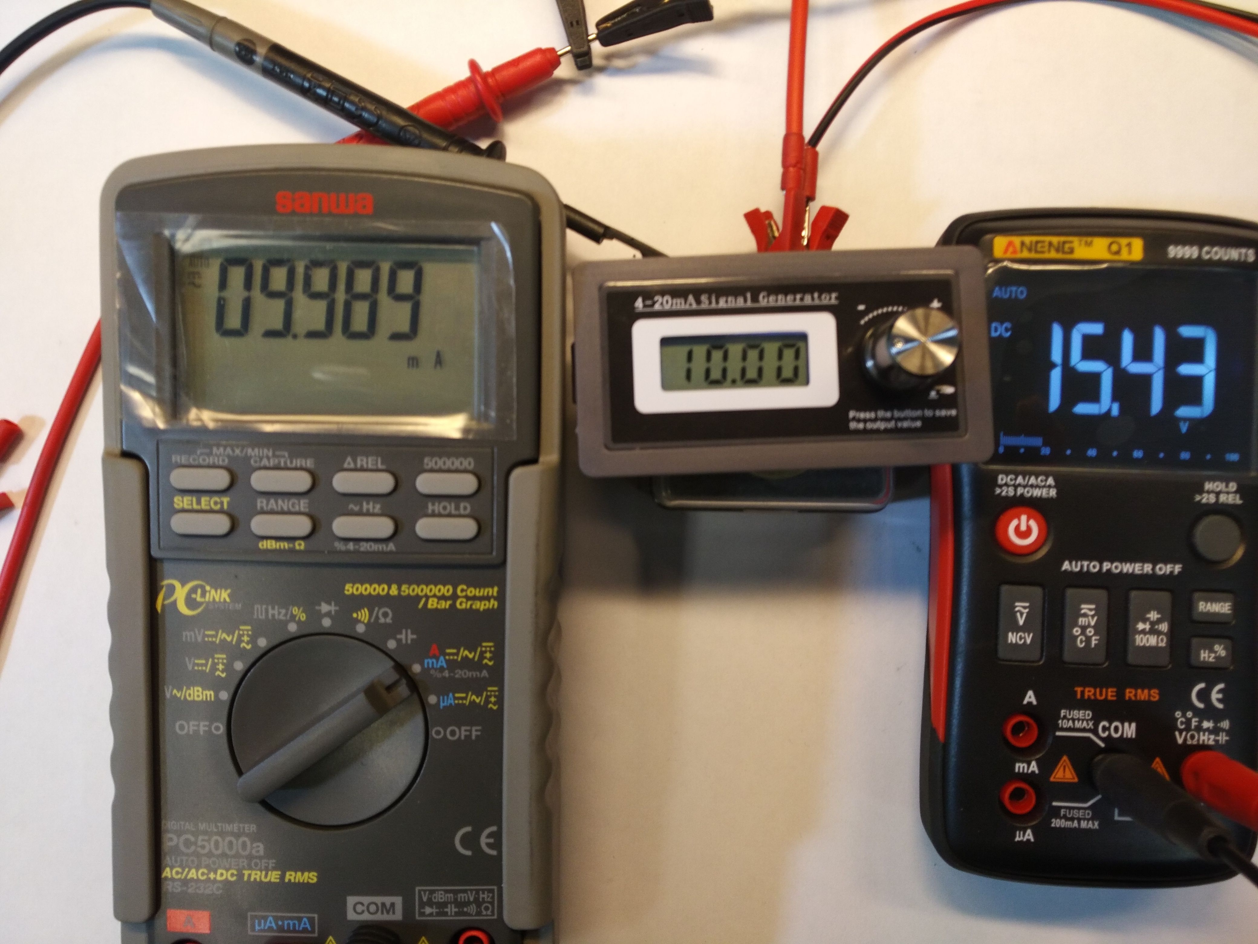
However, after getting rid of the resistor, it turns out that the system works properly at much lower voltages than declared by the manufacturer.

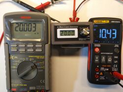
As you can see, 10mA can be obtained with 8V power supply, and 20mA with 10.5V
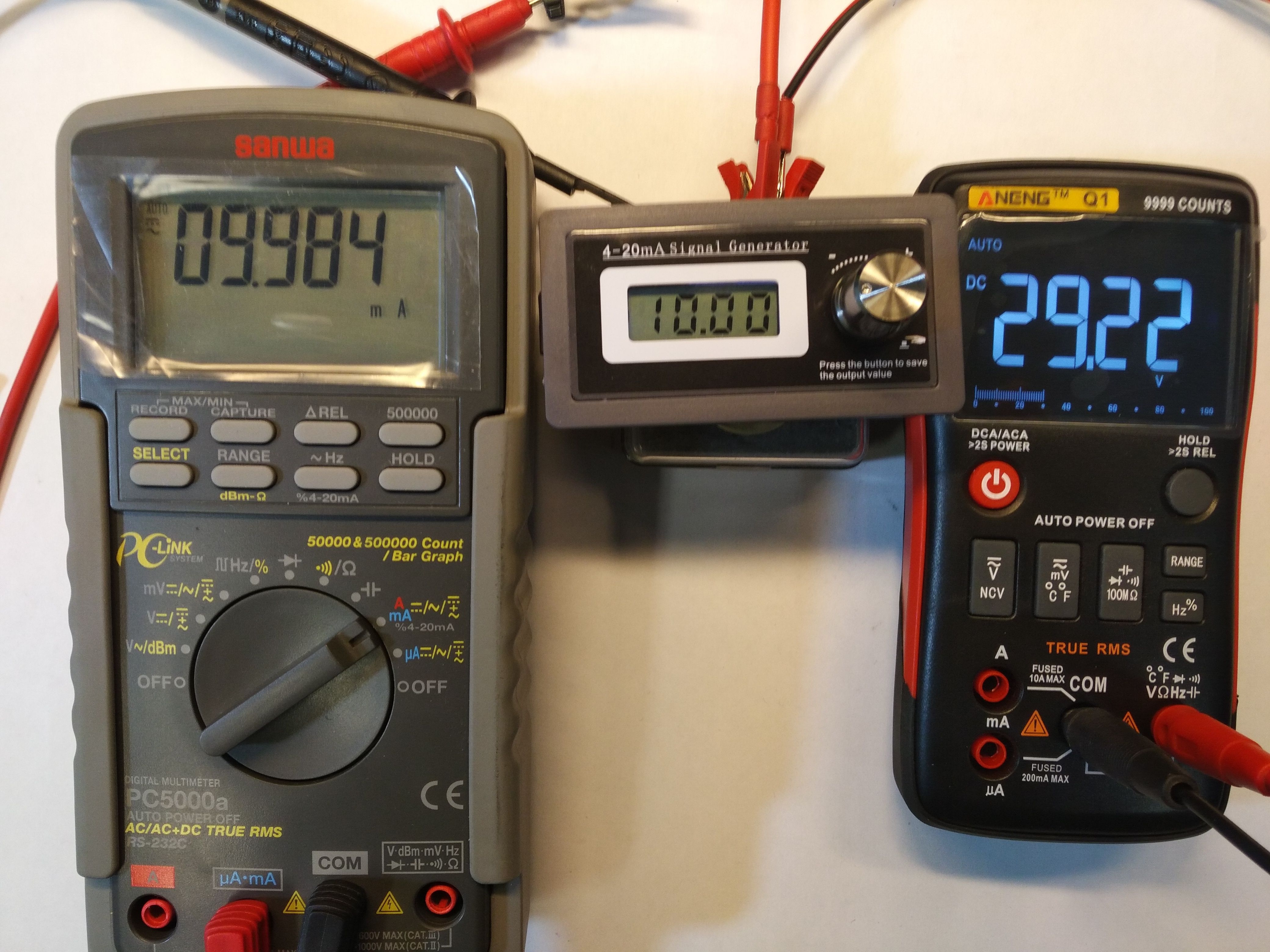
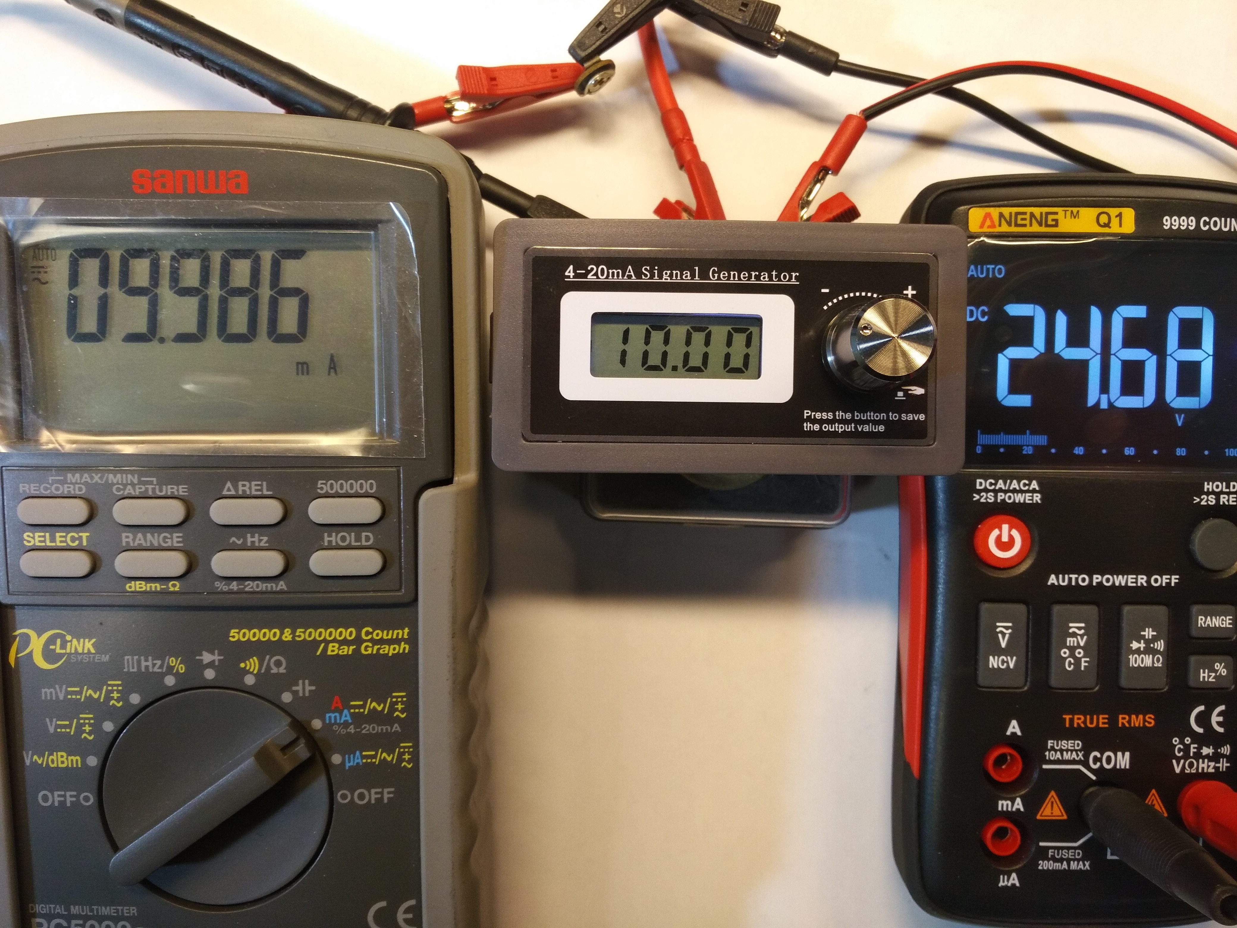
The first experiment was to set the value to 10mA and adjust the power supply to see if the result was stable over the entire range:
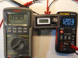

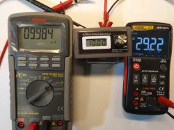
As you can see, the circuit works fine.
The second experiment consisted in setting the power supply to 24V and plugging in a 470? potentiometer. Then, setting the value of 10mA and checking whether turning the potentiometer has any effect on the set current.

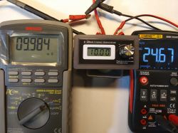
In the first photo, the potentiometer is turned to the extreme left position, in the second - in the middle position, and in the last, in the extreme right position. I did not notice any significant changes while shooting the peer.
One more important piece of information, the Chinese, included the following information in the auction description:
"REVERSE CONNECTION PROTECTION: Our digital signal generator can be inverted connected (two-wire system, no matter positive or reverse connection, the meter can work normally and will not be burnt.)" I didn't check it, but as far as my eyes are concerned, the D2 is a rectifier bridge (I don't have the device with me to check now).
EDIT 01/21/2019, 16:50: As you asked about the possibility of including a resistor in the circuit to get a pseudo voltage standard, I am posting some additional photos with a 100? resistor, unfortunately I did not have such a 1%.

Best regards.
CMS


Comments
1. So it is simply plugged into the tested circuit in series and it does not need to be additionally powered? 2. Is the polarity, plus / minus to which input device connection important? 3. What is the... [Read more]
Are you sure "like hot cakes"? Despite good parameters and nice workmanship, its use is quite limited. If only it could give the reference voltage in the range 1-10V. [Read more]
Probably not because a small group of interested parties - industrial automation. I would probably be tempted, because sometimes I do something on the current loop. Most often, an appropriate power supply... [Read more]
I know but we'd have "two in one" :| It could be two independent circuits on one PCB with one common display showing V and mA simultaneously. What is the acceptable upper limit of the load resistance? ... [Read more]
I join the question. [Read more]
I think that 100? is possible, since the minimum supply voltage is 15V and the maximum voltage drop on this resistance is 100? x 20mA = 2V but what if it is higher. What could be the biggest? [Read more]
You can, but you have to remember that the zero load capacity of such a "voltage source", any physical load of even a few kiloohms will lead to an error. Insert a 500? resistor and you will have a... [Read more]
When called to the board, I answer that I liked this gadget, and I mean testing the circuits in all kinds of 4-20mA sensors. That's why I proposed it. More and more different types of sensors are entering... [Read more]
With a voltage drop across a resistance of 100?, additional resistance> 10k? will introduce an "acceptable error" [Read more]
In such a room unit it is sometimes useful to scale 0-100%, 4mA - 0%, 20mA -100%. I use a fast setter made on the LM317, additionally I connect a milliammeter, and here there are two in one, a setter and... [Read more]
Yes. I added information in the first post: I have no idea but I think no more than 30mA No. The potentiometer was connected in series and the purpose of the test was to check if the... [Read more]
Perfect illustration of the answer to my question. Thank you. I think with a tolerance of 0.1% this would be a good amateur voltage pattern, not a pseudo voltage pattern. :| Only now did I understand... [Read more]
Author, you missed one letter in my Nick. ;) [Read more]
Sorry, I have already corrected. [Read more]
Has anyone checked such a setter? more universal it would seem Handheld Current Voltage Signal Generator Analog Simulator Output 0-10V 0-20mA https://pl.aliexpress.com/item/Handheld-Current-Voltage-Signal-Generator-Analog-Simulator-Output-0-10V-0-20mA/32962784440.html?spm=a2g17.10010108.1000016.1.73771d48g60xNu&isOrigTitle=title... [Read more]
Read this (actually watch) http://www.conradhoffman.com/MML%20files/2_null_p4.jpg On this basis, you can build a fairly accurate device for adjusting at specific points (adjustment), it is true that... [Read more]
Professional 0-10V, -20mA setpoint unit for comparison: https://www.dacpol.eu/pl/zadajniki-sygnalow-analogowych/product/pototykiometer-cyawod_EDP2041_SISEL it's also not bad in terms of price ;) ... [Read more]
Nice equipment, although serial power has its drawbacks. After disconnecting from the target tested element (e.g. diode), the power is turned off and everything resets. What does "reaching" the set current... [Read more]
If you remember the setting by pressing the pulse generator knob, then after a power failure, the value will be the same as before. [Read more]