Active load syndrome
There are many designs for a device that is one of the elements of the workshop equipment and it takes a while to find a diagram or description of the construction.
When creating the design that I want to devote to this description, I was guided by the need to separate high power and the possibility of using it to measure the capacity of the batteries.
The whole is divided into 3 functional parts.
1. Team tasking and monitoring working conditions
2. Executive member
3. Auxiliary circuit
Ad 1.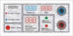
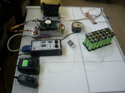
I will briefly describe the meaning of the various elements of the faceplate.
The device, apart from being a typical load, e.g. of the tested power supply, has the ability to determine battery capacity, hence 2 potentiometers.
Red sets the value of the load current. in the range from about 0.1 ÷ 10 A.
Blue allows you to define the voltage at which automatic shutdown is to take place.
3 visible meters provide information about the current operating status, and the third (higher digits) switches on automatically when the voltage on the load transistors is alarmingly high.
Here's a little note.
It is a construction for workshop use, made of the so-called przydasiów. It has a few security features, but it's not to put it mildly ... foolproof. Hence the third meter that allows you to find out about the amount of power on the working transistors.
Although there is thermal protection against overheating, improper setting of operating conditions can damage the transistors before they can heat the heat sink.
Of course, we are talking about the extreme values of current and voltage.
Ad 2.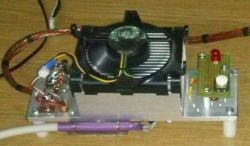
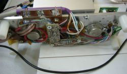
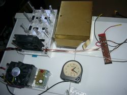
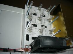
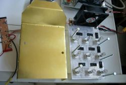
It is a part of the whole housing working transistors, a heat sink, a shunt, and a system that monitors the temperature of the heat sink and provides emergency shutdown in case the fan fails to cool down. LED indicates tripping.
Ad 3.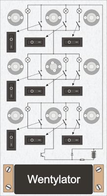
This is an additional element that allows you to distribute the power. Some go to the transistors, the rest of the power is dissipated in the light bulbs.
The loading of the tested power supply does not require too complicated explanations.
Switching on is carried out with the Start / Stop button. Earlier, you can set the value of the load current and voltage to a value lower than the voltage of the tested power supply (I will describe this lower later).
After the operation starts (Start), the meters show the current values of current and voltage, which is indicated by the "Actual value" LED. Every 5 seconds, the indication switches to reminding the previously set value, which is indicated by the green diode.
This operating mode allows you to see when the load comes out of the assumed DC phase. It is possible to imagine a situation where we assume that the power supply is loaded with, for example, a current of 5 A, but due to the total resistance, the maximum current can reach a maximum of 4 A. It will come out right away.
Measurement of the battery capacity requires precise determination of the voltage value at which the measurement is to end. Obviously, the current value must also be set.
Time measurement is needed to take measurements. I used a long-standing clock in the drawer here.
It is turned on automatically when the Start button is pressed and stops when the process is finished (blue LED).
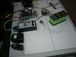
Sorry for the poor photo quality. While making them, I didn't think about describing this topic.
When creating the design that I want to devote to this description, I was guided by the need to separate high power and the possibility of using it to measure the capacity of the batteries.
The whole is divided into 3 functional parts.
1. Team tasking and monitoring working conditions
2. Executive member
3. Auxiliary circuit
Ad 1.

I will briefly describe the meaning of the various elements of the faceplate.
The device, apart from being a typical load, e.g. of the tested power supply, has the ability to determine battery capacity, hence 2 potentiometers.
Red sets the value of the load current. in the range from about 0.1 ÷ 10 A.
Blue allows you to define the voltage at which automatic shutdown is to take place.
3 visible meters provide information about the current operating status, and the third (higher digits) switches on automatically when the voltage on the load transistors is alarmingly high.
Here's a little note.
It is a construction for workshop use, made of the so-called przydasiów. It has a few security features, but it's not to put it mildly ... foolproof. Hence the third meter that allows you to find out about the amount of power on the working transistors.
Although there is thermal protection against overheating, improper setting of operating conditions can damage the transistors before they can heat the heat sink.
Of course, we are talking about the extreme values of current and voltage.
Ad 2.


It is a part of the whole housing working transistors, a heat sink, a shunt, and a system that monitors the temperature of the heat sink and provides emergency shutdown in case the fan fails to cool down. LED indicates tripping.
Ad 3.

This is an additional element that allows you to distribute the power. Some go to the transistors, the rest of the power is dissipated in the light bulbs.
The loading of the tested power supply does not require too complicated explanations.
Switching on is carried out with the Start / Stop button. Earlier, you can set the value of the load current and voltage to a value lower than the voltage of the tested power supply (I will describe this lower later).
After the operation starts (Start), the meters show the current values of current and voltage, which is indicated by the "Actual value" LED. Every 5 seconds, the indication switches to reminding the previously set value, which is indicated by the green diode.
This operating mode allows you to see when the load comes out of the assumed DC phase. It is possible to imagine a situation where we assume that the power supply is loaded with, for example, a current of 5 A, but due to the total resistance, the maximum current can reach a maximum of 4 A. It will come out right away.
Measurement of the battery capacity requires precise determination of the voltage value at which the measurement is to end. Obviously, the current value must also be set.
Time measurement is needed to take measurements. I used a long-standing clock in the drawer here.
It is turned on automatically when the Start button is pressed and stops when the process is finished (blue LED).
Sorry for the poor photo quality. While making them, I didn't think about describing this topic.


Comments
Interesting project. I'm waiting for some schematics or part 2. regards [Read more]
Part 2 still warm, just finished. [Read more]
For years, I have been struggling with an unpleasant ailment that has been afflicting me since I was a child - my innate laziness. I am making progress in this matter and, in the case of more important... [Read more]