Elektroda.com
Elektroda.com
X
This content has been translated flag-pl » flag-en View the original version here.
  • Hello,

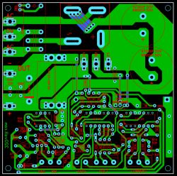
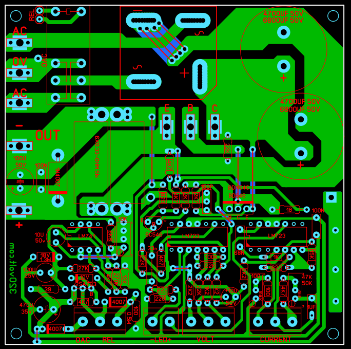
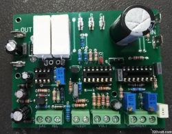
    Tried the 0-30v 0-10a power supply circuit works fine, sprint layout drawings on PCB and gerber files. velleman k7200 new printed circuit board control card Single layer PCB 91.6X72.2mm

    This laboratory power supply will undoubtedly be a valuable device for both a professional electronics engineer and an amateur.

    PARAMETERS:
    - continuously adjustable output voltage from 0 to 30V;
    - output current limitation adjustable from 0 to 10A;
    - current limited signaling by means of a LED diode;
    - output current: 8A continuous, 10A peak;
    - maximum ripple 0.5mVsk;
    - short circuit protection;


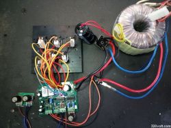
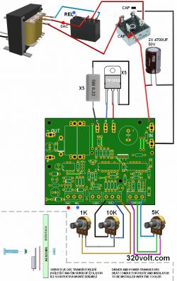
    Laboratory power supply 0-30V 0-10A Laboratory power supply 0-30V 0-10A Laboratory power supply 0-30V 0-10A Laboratory power supply 0-30V 0-10A Laboratory power supply 0-30V 0-10A Laboratory power supply 0-30V 0-10A

    Download: https://bit.ly/3j7xTvY

    Cool? Ranking DIY
    About Author
    gevv
    Level 12  
    Offline 
    gevv wrote 92 posts with rating 466. Live in city istanbul. Been with us since 2007 year.
  • #2
    damian1115
    Level 36  
    It is a pity that you did not describe this power supply, at least a little in your own words. Write something about him.
  • #3
    Freddy
    Level 43  
    @gevv What's yours here, because apart from the first sentence, everything comes from the source page.
    You may be the author of it, but nothing seems to indicate it yet.
  • #4
    gevv
    Level 12  
    Hello,

    Excuse me. What category is suitable for sharing?
  • #5
    Slawek K.
    Level 35  
    My friend is from Turkey, so it is difficult for him to write in Polish.

    Greetings
  • #6
    Freddy
    Level 43  
    gevv wrote:
    Excuse me. What category is suitable for sharing?
    It may be this, but only after you complete the description - it must be more precise, not just one sentence.
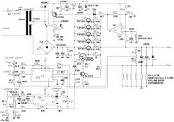
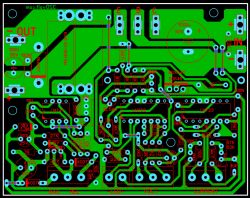
    Show schematic and PCB.

    If you have a problem with writing in Polish, write a description in English and one of your colleagues will try to translate it into Polish.
  • #7
    gevv
    Level 12  
    Hello,

    Corrected. Thanks.
  • #8
    398216 Usunięty
    Level 43  
    Since the "laboratory power supply" should (?) Have a housing, current and voltage meters? As it stands it is just an idea for a power supply. In addition, I miss the oscillograms of the output voltage (ripple) under the nominal load (max U and max I).
    And besides - an interesting structure.
  • #9
    eurotips
    Level 39  
    Plusik for originality and complete documentation.
    The housing depends on the transformer and heat sink you have.
    I do not believe in the 0.5mV ripple at the output.
  • #10
    Freddy
    Level 43  
    @gevv Thanks for the correction - greetings and congratulations on the nice design.
  • #11
    gevv
    Level 12  
    Hello,

    File updated, motherboard and DC 100X100mm PCB connection

    Laboratory power supply 0-30V 0-10A
  • #12
    Anonymous
    Level 1  
  • #13
    321Tobiasz123
    Level 7  
    Cool design. What is the approximate cost of parts for the construction of such a power supply?
  • #14
    Gismot
    Level 18  
    The filtration in the power supply is very poor, the 10mF capacitor will not live for too long, because you exceed its operating current (it will simply boil).
  • #15
    Freddy
    Level 43  
    Gismot wrote:
    The filtration in the power supply is very poor, the 10mF capacitor will not live for too long, because you exceed its operating current (it will simply boil).
    Where do you see a 10mF capacitor because I can't find it?
  • #16
    CodeBoy
    Level 31  
    Freddy wrote:
    Gismot wrote:
    The filtration in the power supply is very poor, the 10mF capacitor will not live for too long, because you exceed its operating current (it will simply boil).
    Where do you see a 10mF capacitor because I can't find it?


    In the video 0:41 the question is whether only for testing or ultimately.
  • #17
    eurotips
    Level 39  
    Freddy wrote:
    Where do you see a 10mF capacitor because I can't find it?


    C11 and C12 in the diagram, on pcb you can see in # 11 that he has a lot of space for them.
    Let's face it, if someone actually uses a solid hit and will constantly charge 5A or more,
    it needs to add a solid battery elek. And he has to find a way to mount this battery, one 100mF capacitor is a bad idea, a better solution is 10x 10mF and a dedicated pcb only underneath it with holes for a solid mounting.
  • #18
    Freddy
    Level 43  
    Well, it's 2x4700uF, not a 10mF capacitor, and that's the difference.
    Gismot wrote:
    because you exceed its current (it will just boil).
    I am curious about the justification of this current of work.
    eurotips wrote:
    a better solution is 10x 10mF
    eurotips wrote:
    one capacitor with a capacity of 100mF
    Are you not exaggerating with these capacities?
  • #19
    398216 Usunięty
    Level 43  
    Freddy wrote:
    I am curious about the justification of this current of work.
    I must admit that I would also like to learn something new ... How would the operation with 100Hz supercharging "boil" a capacitor?
    Freddy wrote:
    eurotips wrote:
    a better solution is 10x 10mF
    eurotips wrote:
    one capacitor with a capacity of 100mF
    Are you not exaggerating with these capacities?
    I would not like to be smart, but does it not depend (probably about the ripple Eurotips?) On the difference in voltages before / after stabilization? If so, it can be even 100uF, but for a large decrease in stabilization. So - yes - the larger the capacity, the better, but without exaggeration.
    Freddy wrote:
    it is 2x4700uF, not 10mF capacitor, and that's the difference.
    Well, it is ... and it is twice :) lower ESR means higher current efficiency in a pulse. A colleague of eurotips probably read too much, not fully confirmed news ...
    eurotips wrote:
    a better solution is 10x 10mF
    - in any case, the above quote proves it.
  • #20
    worlinx
    Level 12  
    As for me:
    1. 2x15v on a hit is not enough for a 0-30v 10A power supply
    2. 2x4m7 in filtration - too little, but see point one
    3. it is not feasible to achieve the range of 0V and 0mA without supporting the output with a source "sucking" the current from the output, e.g. a resistor connected to a negative voltage
    4.this heat sink for power transistors is too small, but the fan should fix the problem.
  • #21
    timothy1989
    Level 11  
    I made this power supply in pcb version no.2, the toroid I have is 2x13.5VAC, I gave 10mF and 6300uF capacitors, and I can say that I am satisfied (with myself) everything works beautifully. All I had to buy was the bdx54 transistor, the rest I found among various piles of junk in the depths of my workshop. When I put everything together (i.e. housing, front panel, multimeter and soft start to the toroid) I will throw some photos. I am also thinking about thermal protection, something like a 95-degree thermal fuse and a relay (because I have 15 pcs in stock), which would cut off the power to the ICs and light the indicator. This can be easily connected to the jumper next to the capacitor C10 and the diode D2. I tested the power supply on a bd249 bolted to a large heat sink, it lasted about 5 minutes on a short circuit at 5A, and the capacitors (except C9 of course) were as cold as Bob Marley.
  • #22
    Bieda z nędzą
    Level 35  
    What is the R36 resistor for?
  • #23
    AdamC
    Level 28  
    Bieda z nędzą wrote:
    What is the R36 resistor for?

    Probably, if you have a relay for lower voltage, it can be useful.
  • #24
    Bieda z nędzą
    Level 35  
    I guess so. I am also concerned about the relatively small total capacity of the main power supply filter capacitors; less than 10000uF for this limit output current.
  • #25
    398216 Usunięty
    Level 43  
    Bieda z nędzą wrote:
    I am also concerned about the relatively small total capacity of the main power supply filter capacitors
    It was already about it.
  • #26
    Jawi_P
    Level 35  
    eurotips wrote:
    one capacitor with a capacity of 100mF is a bad idea, a better solution is 10x 10mF and a dedicated pcb only underneath it with holes for a solid mounting.

    And soft-start will be mandatory, not optional.
    The second thing is that by roughly calculating the filter capacity for a maximum current of 10A, and the ripple level of 2V, I ended up with 0.05F. And that's a lot already.
    I would reduce C9 as much as possible and / or use a current source at the output to discharge this C.
    Since there is D3, the fuse at the output would also be useful?
  • #27
    timothy1989
    Level 11  
    Jawi_P wrote:
    eurotips wrote:
    one capacitor with a capacity of 100mF is a bad idea, a better solution is 10x 10mF and a dedicated pcb only underneath it with holes for a solid mounting.

    And soft-start will be mandatory, not optional.
    The second thing is that by roughly calculating the filter capacity for a maximum current of 10A, and the ripple level of 2V, I ended up with 0.05F. And that's a lot already.
    I would reduce C9 as much as possible and / or use a current source at the output to discharge this C.
    Since there is D3, the fuse at the output would also be useful?


    After all, there is R5 and R23 as well as R6 and R17, it is probably enough to discharge a 100uF capacitor.
    And D3 is not as security? In similar constructions, this diode was supposed to eliminate the negative effects of voltage peaks, e.g. breakdown or reverse battery connection. Of course, I can be wrong, I'm still learning.
  • #28
    398216 Usunięty
    Level 43  
    timothy1989 wrote:
    it's probably enough to discharge a 100uF capacitor.
    It is not about discharging the capacitor, but about the speed of response to the load pulses.
    timothy1989 wrote:
    In similar constructions, this diode was supposed to eliminate the negative effects of voltage peaks, e.g. breakdown or reverse battery connection.
    Not only the battery. After all, there may be a large-capacity capacitor in the powered system? You disconnect the power supply from the power supply, and the "reverse" voltage may appear on the terminals, which is not beneficial ... and the diode gave up the ghost. To avoid this, insert a fuse - a short-term (necessary for the fuse to work) than the diode will withstand (if it is matched to the power supply current) before the fuse blows and thus cuts the load from the power supply system itself.
  • #29
    timothy1989
    Level 11  
    398216 Usunięty wrote:
    timothy1989 wrote:
    it's probably enough to discharge a 100uF capacitor.
    It is not about discharging the capacitor, but about the speed of response to the load pulses.
    timothy1989 wrote:
    In similar constructions, this diode was supposed to eliminate the negative effects of voltage peaks, e.g. breakdown or reverse battery connection.
    Not only the battery. After all, there may be a large-capacity capacitor in the powered system? You disconnect the power supply from the power supply, and the "reverse" voltage may appear on the terminals, which is not beneficial ... and the diode gave up the ghost. To avoid this, insert a fuse - a short-term (necessary for the fuse to work) than the diode will withstand (if it is matched to the power supply current) before the fuse blows and thus cuts the load from the power supply system itself.


    So with this capacitor it was about, for example, the PZC circuit?

    All in all, I was wondering about this fuse (I have it in the rectifier), there will even be a place on the front panel. This is the third similar power supply that I put together, each with some flaws. In the previous one, there was not even this LED on the output. But each had a 100uF / 50V output capacitor.
  • #30
    398216 Usunięty
    Level 43  
    In mine I gave 10uF and it's OK too. But the diode is obligatory. I managed to damage the serial transistor twice without it, so I finally upgraded. (Of course, a different power supply from a different schematic - but the idea is the same)