Hello
I would like to share with you a project that I did some time ago.
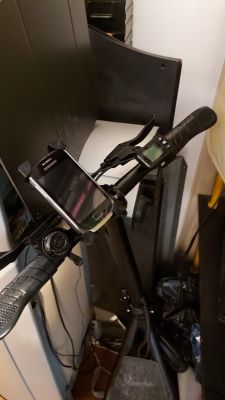
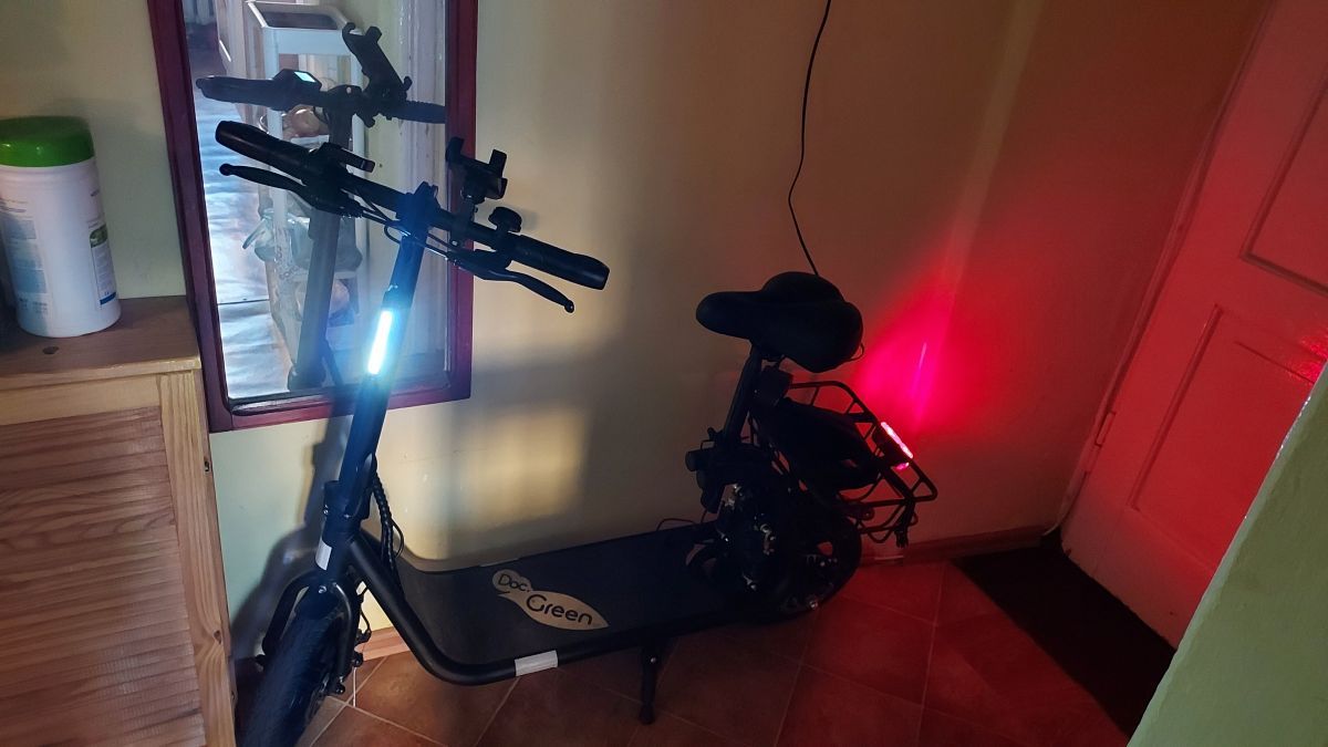
In July, I bought an eclectic scooter in Lidl with a seat and a basket.
I thought that it would be useful to do some security and ordered a GPS locator from the Majfrends.
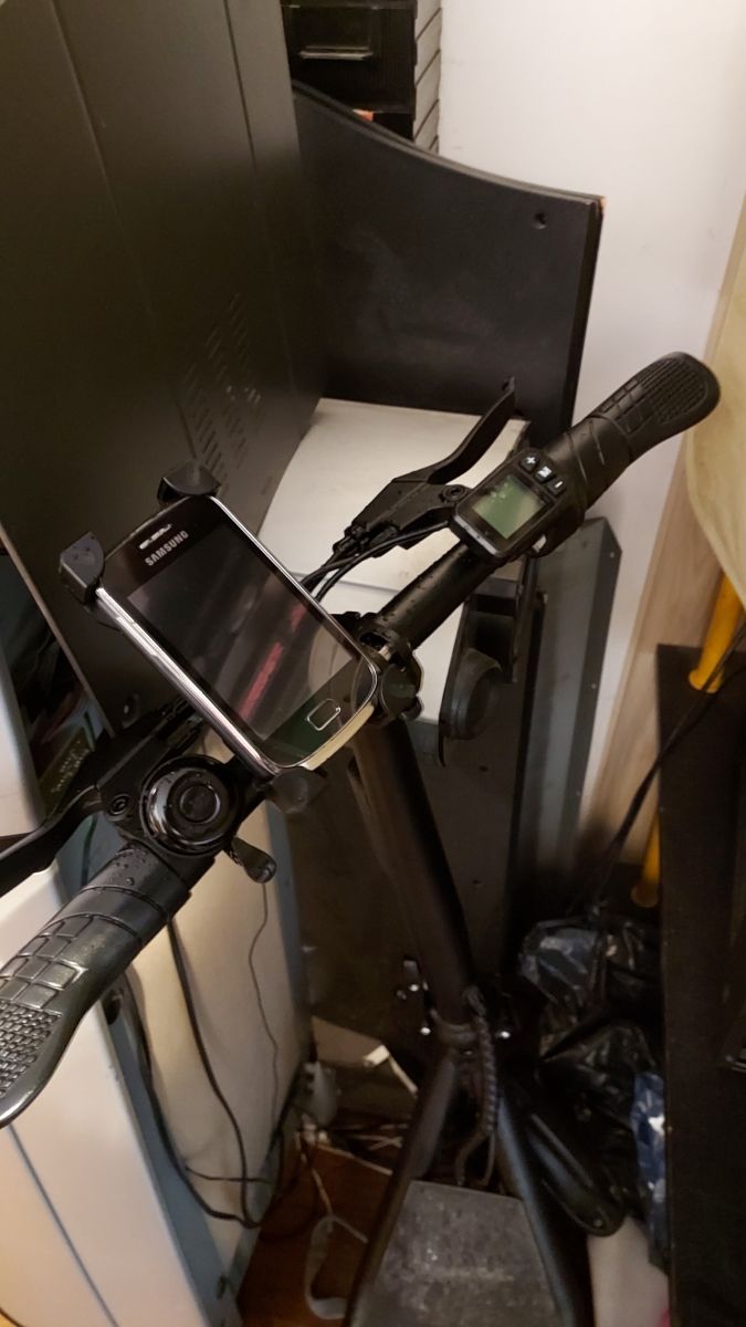
By the way, I thought about a phone charger, the more the phone holder is bought.
This topic inspired me
https://www.elektroda.pl/rtvforum/topic3782282.html and I decided to do a security and in this "some kind" on / off switch.
So to the point.
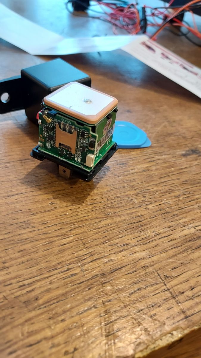
The GPS locator I bought works in the voltage range of 9-90 V, so there is no problem with direct connection to the scooter battery (36 V, charged is about 42 V).
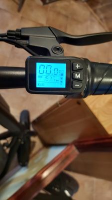
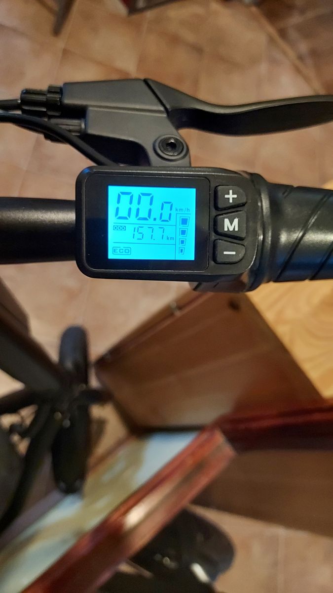
It turned out to be a nice surprise that the voltage value is displayed in the tracking application, which makes it possible to control the state of charge through the application.
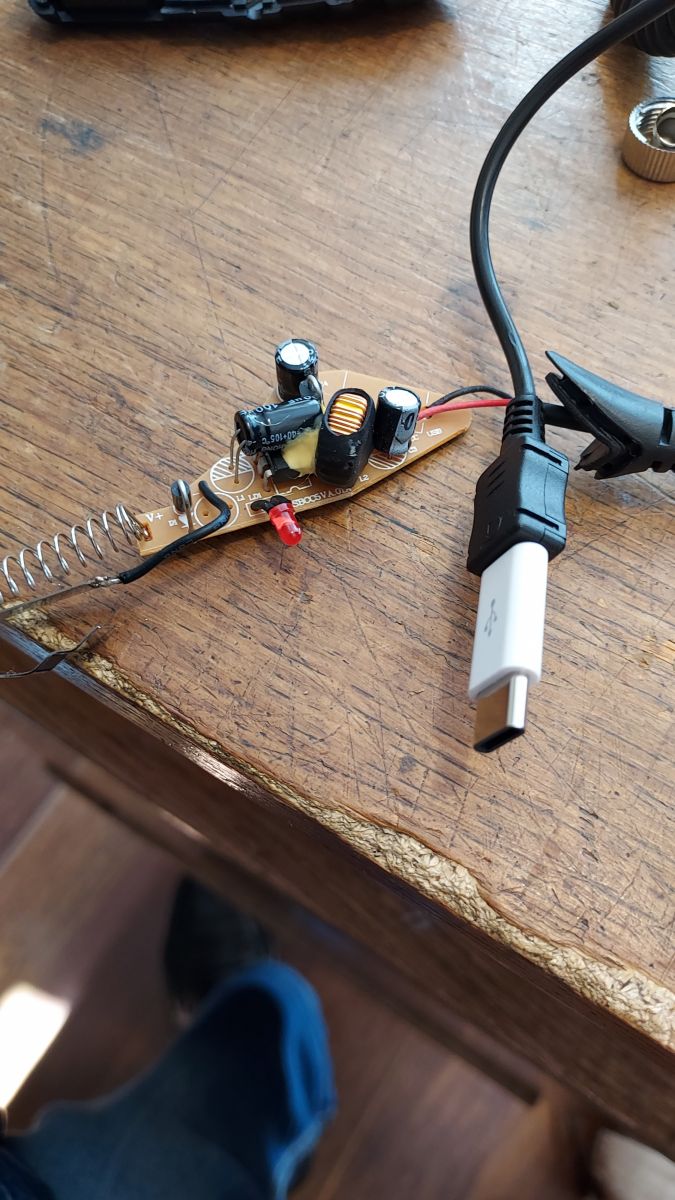
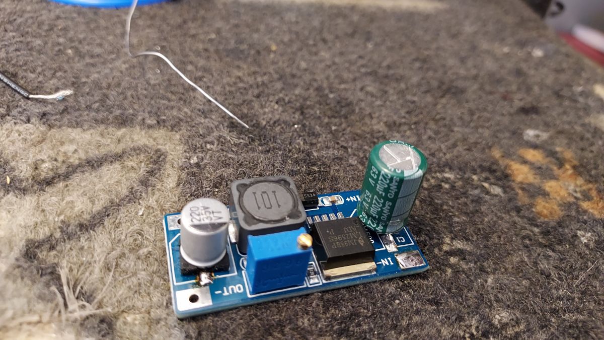
The locator has the ability to remotely cut off the fuel (in the car), which I decided to use as an "kind" on / off switch. Here a small problem arose as it is not a simple mechanical but an electronic relay. It works in the voltage range (9-15 V). Using the Step down converter, I get a voltage of 12 V to power this circuit and the car charger. I bought a weak one-amp charger (it's hard to buy a weak one now, but I managed) so as not to drain the scooter battery too much (7.5 Ah). I added the charger for an emergency if the phone fell.
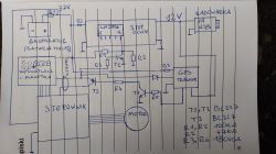
The circuit diagram I used is straightforward, no frills:
First, I had to determine which of the wires gives info from the display-shifters assembly to the controller about turning on the scooter (by holding the M button for a long time).
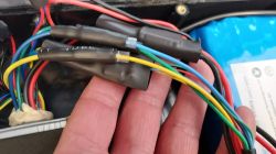
Traditionally sticking pins and using a gauge. In my case it was a blue wire. And this is the only wire that I had to cut to implement the project, I did all the rest of the connections with the scooter wires using quick couplers.
I will now discuss the connections and how it works.
I set the step down circuit based on the LM2596 with adjustable output voltage to 12 V. Foot 5, the chip (i.e. start / stop pin) was desoldered from the board, it was connected to ground, and connected to the external circuit, which shortened it to ground using a transistor T1. The transistor T1 is switched on with the voltage of 36 V through the resistor R3 in series with the diode D1 (no diode in the attached diagram - sorry). The resistance divider R1, R2 supplies a dozen or so volts to the pin 5, the chip in the off state of the scooter and thus the step down converter does not work. This voltage is supplied from the display-lever assembly when the scooter is turned on. So that part of the blue cut wire that I mentioned earlier, from the side of the display. The voltage of 12 V from the converter is fed to the car charger (from which I removed the LED diode for savings, and so it is hidden in the battery and controller container together with the rest of the system), and to the fuel cut-off circuit in the locator. When we give the command "Cut Off Fuel" from the application, the voltage of 12 V is not applied to the base of the transistor T3 through the resistor R5 and thus the transistor T2 will not be controlled. The signal from the display will not go to the controller and the scooter will not work (it shows error E001). When we give the command "Restore Fuel" from the application, 12 V will come out of the locatoron R5 and T3 will turn on, and it will turn on T2 and the 36V signal will reach the controller when we turn on the scooter, and it will start to spin as needed. In addition, I connected the ACC input in the locator with the 36 V output from the display via the D2 diode (both D1 and D2 diodes are 1N4007), this way I also have information in the application about turning on the scooter.
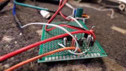
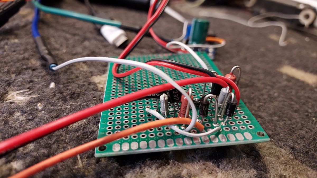
These few additional elements (T1, 2, 3 R1,2,3,4 =, 5 D1,2) were installed and connected on a small mounting plate. Unfortunately, it is such a "better" spider. I didn't have time to make a decent PCB.
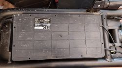
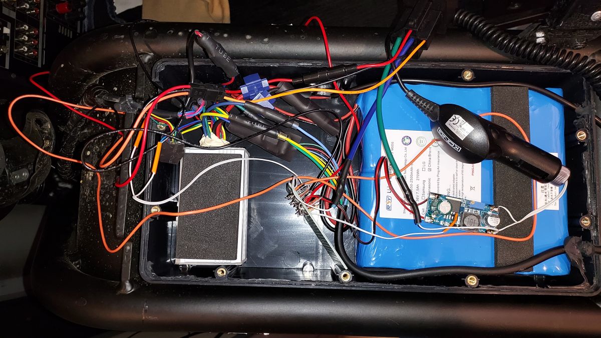
I have hidden everything in the scooter container for the battery and the controller. I re-secured with black silicone. Outside, apart from the phone charging cable, nothing sticks out.
PS Sorry for the chaotically drawn diagram and some mumbling here.
Greetings, if anyone has any questions or comments, I will be very happy to answer and listen.


Comments
Nice design, private scooters arriving, a series of articles on scooter electronics and batteries could do with it. In the meantime, write to me for a gift :) [Read more]
Nice design and an interesting idea. I suspect that not one of the scooter users will try to do something like that. [Read more]
One thing puzzles me. The description states that the locator, during normal operation, gives the voltage that starts the scooter, and if we give the command "fuel cut-off", then the locator does not come... [Read more]
A thumbs up. I would just like to warn you against too much discharge of the battery. 2 years ago I installed a GPS locator on a scooter, in my case it was the iTrackSafe MT-1. It worked fine until after... [Read more]
Interestingly, such a 'scooter' with a saddle is not covered by any regulations, even after the last amendment to the code. They define electric scooters as devices without a seat and as personal... [Read more]
Yes, here is the definition of a scooter and a personal transport device - UTO, but ... is there such a miracle as an electric scooter + saddle = electric moped ??? Please let the law experts have... [Read more]
Unfortunately, it will roll, which is why I have an additional mechanical protection, a chain with a disc brake clasp. Even without turning it on, it goes on anyway. This is how it is constructed. I don't... [Read more]
Please write something about the locator. What model is it, or 2G, what sim card and tariff. Like with tenderness. [Read more]
I didn't want it to look like an advertisement, but this is the product https://pl.aliexpress.com/item/4000842937287.html?spm=a2g0s.9042311.0.0.27425c0fcsUg2N There is the MV730 model. It works... [Read more]
Art. 2. - [Legal definitions] - Road traffic law. Journal of Laws Journal of Laws 2021.450, i.e. | Effective act. Version: July 1, 2021 to: September 3, 2021 Art. 2. [Legal definitions] The terms used... [Read more]
And since 300 W [Read more]
Walk towards the slow moving vehicle. [Read more]
You are sure that the locator works in the range of 9-90 V, because the description only mentions 6-40 V. I am asking because I am wondering whether to mount it to an electric bike that has a 48V batt... [Read more]
Yes, in the description it is 6-40 V, but in the specification (on the auction website) and on the sheet attached to the product it is 9-90 V. And how to believe the Chinese? You can also write an inquiry... [Read more]
I am surprised by the accuracy of the GPS. After all, the locator is hidden under the metal sheet and glides almost on the ground. :-D Pay attention to the validity of the card, because when the operator... [Read more]
Hello At first, I apologize for asking a slightly different question. An unpleasant situation happened to me, namely, I broke into the premises and a large amount of tobacco products was stolen. Reading... [Read more]
And yet it works. I will definitely keep an eye on. I have the receipt in the electronic version on my phone. There is a Scooter 0351450 1 * PLN 999 on the receipt. Polish user manual: EKS 77 folding... [Read more]
I have been wondering about this locator for some time and my friend encouraged me :-D But I have a question, what do you need to set for it to work in the application? I fight him and he is in China... [Read more]
I watched quite reliable material on this "scooter" classified as a different vehicle. Moving on public roads must be insured - civil liability. It seems the material was about a collision and a claim... [Read more]