FAQ
TL;DR: ATtiny13 dedicates only 16 B of 1 kB flash (1.6 %) to emulate the EEPROM, and “clock stretching just works” [Elektroda, bobeer, #19750015; Microchip, 2022]. The tiny MCU drops straight onto the Saleae-clone board, lets you hop between USBeeSX, Saleae, or Cypress default IDs by power-cycling 2–4 times inside 3 s, and costs below $0.60 [Elektroda, bobeer, #19750015; DigiKey, 2023].
Why it matters: One 50-cent MCU revives dead logic-analyser clones and adds multi-profile VID/PID switching without extra parts.
Quick Facts
- MCU: ATtiny13A, 1 kB flash, 64 B SRAM, 9.6 MHz RC ±10 % [Microchip, 2022]
- Emulated EEPROM: 16 bytes, read-only, no pointer-load command [Elektroda, bobeer, post #19750015]
- VID/PID modes: Saleae 0x0925/0x3881, USBeeSX 0x04B4/0x8613, default Cypress 0x04B4/0x8613 [Cypress, 2020; Elektroda, bobeer, #19750015]
- Mode change trigger: 2–4 power cycles within 3 s window [Elektroda, bobeer, post #19750015]
- ATtiny13A price: US $0.56 @1 k qty [DigiKey, 2023]
What issue does replacing the 24LC02 with an ATtiny13 solve?
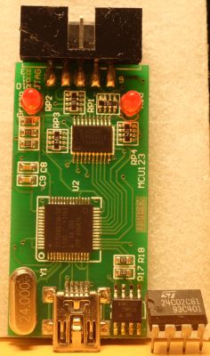
Corrupted EEPROM in cheap Saleae clones leaves the CY7C68013A unrecognised. The ATtiny13 stands in as a fixed 16-byte ROM, restoring enumeration and adding selectable USB identities: Cypress default, USBeeSX, or Saleae [Elektroda, bobeer, post #19750015]
How exactly does the VID/PID switch work?
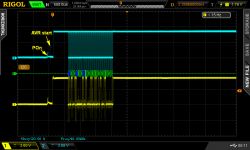
The firmware counts brown-outs. If the analyser is powered 2–4 times within 3 s, it advances to the next profile: default, USBeeSX, then Saleae. Normal plug-and-unplug leaves the profile unchanged [Elektroda, bobeer, post #19750015]
What PCB modifications are needed to fit the ATtiny13?
Solder the ATtiny13 into the SOIC-8 EEPROM footprint. Lift or cut the RESET pin trace so an ISP clip can reach it. The author cut two ground traces to permit in-circuit re-flashing [Elektroda, bobeer, post #19750015]
Can the host write new data to the emulated EEPROM?
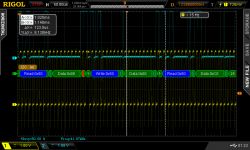
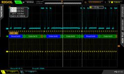
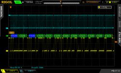
No. Write commands are ignored. Reads beyond byte 15 wrap to byte 0, and the pointer-load command is unimplemented. The Cypress bootloader reads sequentially, so operation remains normal [Elektroda, bobeer, post #19750015]
Does clock stretching operate correctly?
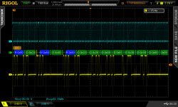
Yes. The code holds SCL low until data is ready; the CY7C68013A tolerates up to 25 µs stretching, and the demo stays below 10 µs [Cypress, 2020; Elektroda, bobeer, #19750015].
What resources does the firmware consume on the ATtiny13?
The HEX occupies 148 bytes, leaving 85 % of flash free. Only 6 bytes of SRAM hold the mode counter and buffers. At 9.6 MHz, the MCU spends under 12 % of cycles serving 400 kHz I²C traffic [Elektroda, bobeer, #19750015; Microchip, 2022].
What happens if the host uses random-access reads?
Drivers that issue the I²C pointer-load command will reread byte 0 because the instruction is ignored. On non-Cypress hosts that expect random access, enumeration could fail—an important edge case [Cypress, 2020; Elektroda, bobeer, #19750015].
How do I trigger a mode change quickly?
- Plug the analyser in, then unplug immediately.
- Repeat step 1 twice more so total time stays < 3 s.
- Plug in once more; Device Manager shows the next VID/PID.
The selected profile is stored in EEPROM and survives power loss [Elektroda, bobeer, post #19750015]
Can I still flash the ATtiny13 once it is soldered?
Yes. Keep RESET accessible; an ISP clip with 5 V and ≤200 kHz SCK can re-flash the chip in about 3 s for a full 1 kB image [Microchip, 2022; Elektroda, bobeer, #19750015].
Will Sigrok show 16 channels after removing the EEPROM?
With no EEPROM (or if ATtiny13 is removed), the CY7C68013A exposes its default descriptor. Sigrok enables 16 channels, but channels 8–15 sit idle unless you add an extra 74HC245 buffer stage [Sigrok Wiki; Elektroda, bobeer, #19750015].
Are there alternative MCUs for larger emulated EEPROMs?
Pin-compatible ATtiny25/45/85 parts offer 2–8 kB flash, letting you emulate up to 256 bytes. They still satisfy the 25 µs clock-stretch limit at 400 kHz [Microchip, 2022].
Where can I get the source code and licence?
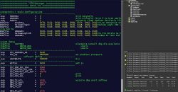
The thread attachment contains C source and HEX. The author labels it "do-what-you-want"; ask for written permission before commercial distribution [Elektroda, bobeer, post #19750015]


Comments