Thermal efficiency is a critical factor in the reliability of electronic systems. Overheating of components can cause irreparable damage, compromise system stability and shorten component life. For this reason, the selection of an appropriate heatsink is critical to ensure that electronic components operate reliably and safely.
In this article, we will examine different forms of heatsinks used to cool down a SiC MOSFET, which is widely used in power systems. Different shape and material solutions will be experimented with to evaluate their effectiveness in heat management. The objective of this experimentation is to provide a general understanding of the thermal performance of different heatsinks and to identify an efficient solution for heat dissipation in a MOSFET. This information will be useful for electronic designers who need to select the most suitable heatsink for their solutions.
Candidate heatsinks
Electronic heatsinks are critical components in many electronic applications, particularly in the dissipation of heat generated by electronic components, such as transistors and MOSFETs. The shape of electronic heatsinks has a significant impact on how they dissipate heat and thus on the performance of electronic components. They are usually constructed using materials with high thermal conductivity, such as aluminum or copper, and have broader surface area to increase the dissipation area. The latter also affects air circulation around the component. The shape of the surface is also an important factor for the purpose of dissipation effectiveness. The material used to construct the heatsink is also an important factor in its ability to dissipate heat. A heatsink built with aluminum has lower thermal conductivity than a heatsink built with copper, but it can be lighter and cheaper. Copper has a higher thermal conductivity, making it a more suitable choice for applications in which heat dissipation is critical. The thermal-dissipation tests performed with the TO-220 package (see Figure 1) are used to evaluate its ability to handle the heat produced.
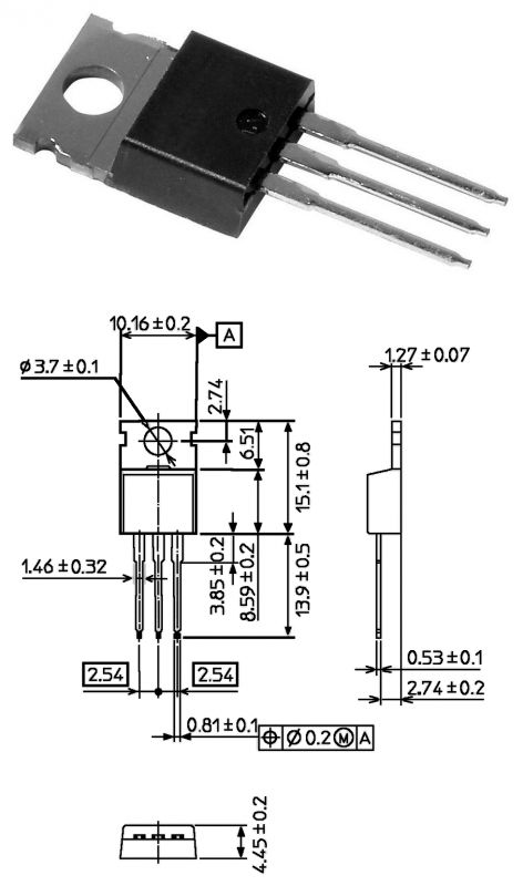 Figure 1: The TO-220 package, widely used for transistors and MOSFETs
A heatsink is essential for proper operation of a power device, and its absence would cause it to operate at unacceptable temperatures, even for lighter applications. As mentioned earlier, heatsinks can be made of different materials; therefore, designers must find a good compromise between proper heat dissipation and the cost of the heatsink. One of the key parameters is thermal conductivity, a parameter that identifies the ability of a substance to transmit heat through thermal conduction. The below table shows this characteristic of some materials.
| Material | Thermalconductivity at 20°C (W/mK) |
| Steelwith 5% Ni | 29 |
| Steelwith 30% Ni | 105 |
| Water | 0.63 |
| Aluminum | 210 |
| Air | 0.026 |
| Silver | 420 |
| Iron | 50 |
| Nickel | 60 |
| Gold | 300 |
| Brass | 80 |
| Lead | 35 |
| Copper8900 | 395 |
| Zinc | 110 |
As can be seen in the table, the materials used the most when building heatsinks are aluminum, silver, gold and copper. It is obvious that silver and gold are not cost-effective at all.
The exposed surface area
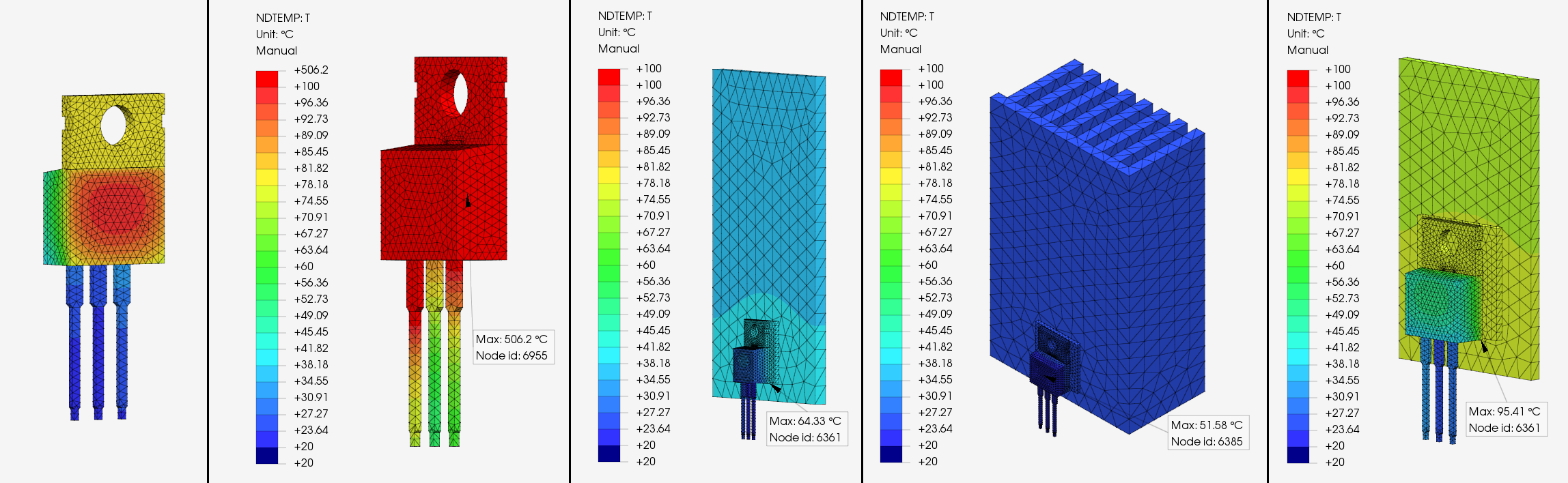
The simulation tests carried out in this section concern the maximum temperature reached by the device, changing the heatsink surface (of aluminum) exposed to air with a thermal coefficient of 0.025 mW/mm2/°C and a temperature of 20°C. In addition, the device is subjected to a power of 30 mW/mm2 on the back surface. Figure 2 shows the results obtained from the simulations and, more importantly, the theoretical maximum temperatures reached by the devices during system operation. The simulations cover the following scenarios, with a temperature scale between 20°C and 100°C:
• Device operating under the above conditions without any heatsink. The maximum temperature reached is about 506°C, for safe destruction of the component.
• Device operating with a parallelepiped-shaped heatsink, with an exposed surface area of 8,780 mm2. The maximum temperature reached is about 64°C and the average temperature of the heatsink is about 36°C, for correct operation of the device.
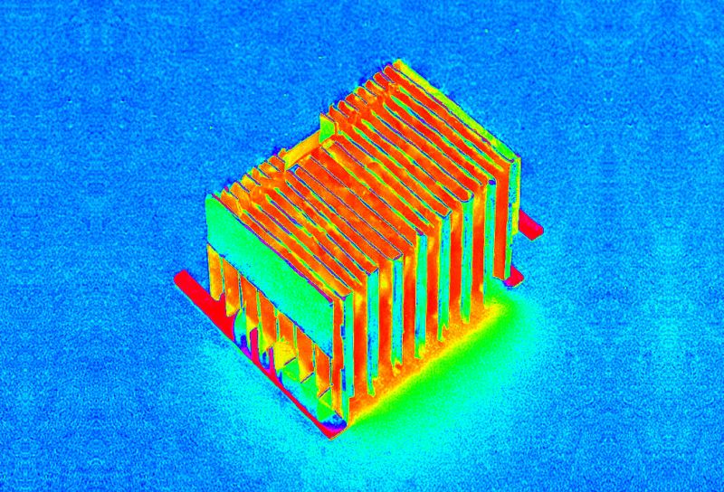
• Device operating with a heatsink of complex shape, with many fins widening the exposed surface area by 41,080 mm2. The maximum temperature reached is about 51°C and the average temperature of the heatsink is about 26°C, for optimal device operation.
• Device operating with a parallelepiped-shaped heatsink, with an exposed surface area of 2,195 mm2. The maximum temperature reached is about 95°C and the average temperature of the heatsink is about 73°C, for good device operation.
 Figure 2: The results of the simulations in relation to the exposed surfaces of the heatsinks.
The results can be summarized in the following table:
| Exposedsurface (mm2) | Maximumtemperature (°C) |
| 0 | 506.2 |
| 8,780 | 64.33 |
| 41,080 | 51.58 |
| 2,195 | 95.41 |
To further lower the thermal resistance of the heatsink, it can be subjected to forced convection, using a fan. In this case, the thermal resistance is proportional to the air velocity, and the temperatures reached by the system are lower.
Conclusion
The thermal characteristics of a system are influenced by so many variables, such as the shape of the profile, the exposed cooling surface, the air velocity, the material used and so on. The exposed surface area of a heatsink is considered one of the most important characteristics, as it directly influences heat dissipation efficiency. The greater the exposed surface area, the greater the heatsink’s ability to transfer heat from the warm component to the surrounding environment, thus reducing the component’s temperature. This is especially important in applications that require precise temperature control, such as in precision electronics or systems with high temperatures. The choice of the optimal size for a heatsink also depends on the amount of heat that needs to be dissipated, the availability of space and the configuration of the cooling system. In general, a larger heatsink may have more exposed surface area and thus greater capacity to dissipate heat. However, a heatsink that is too large may also be less efficient due to greater resistance to airflow, which may reduce heat-transfer capacity. In addition, too broad a heatsink may require more powerful ventilation and thus be more expensive to implement.

Comments
Buen dia Maurizio, tienes algun estudio sobre los disipadores que usan barras cilindricas en lugar de aletas, pd. muy instructiva tu publicacion, Gracias [Read more]
Thank you for your comment. I don't have a study about that. But I think this article would be a good reference. Please let me know. https://www.mdpi.com/1996-1073/15/20/7583 . And if you are a fan of... [Read more]