Hi,
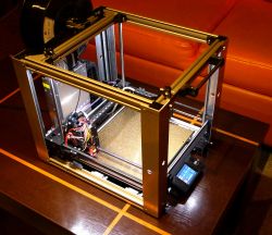
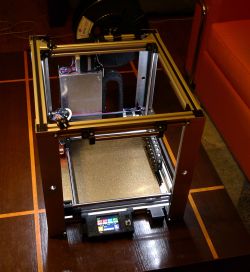
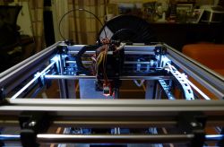
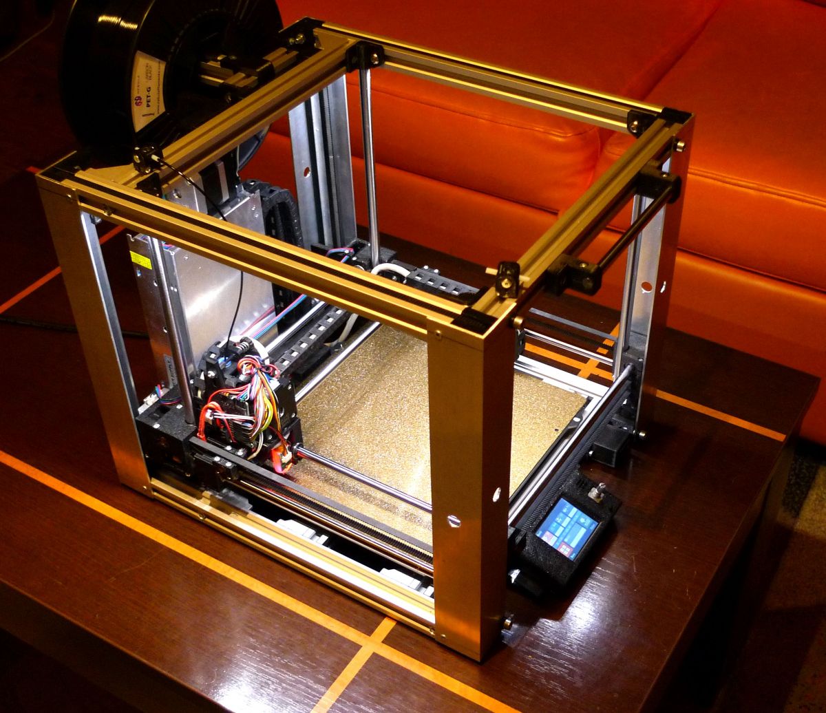
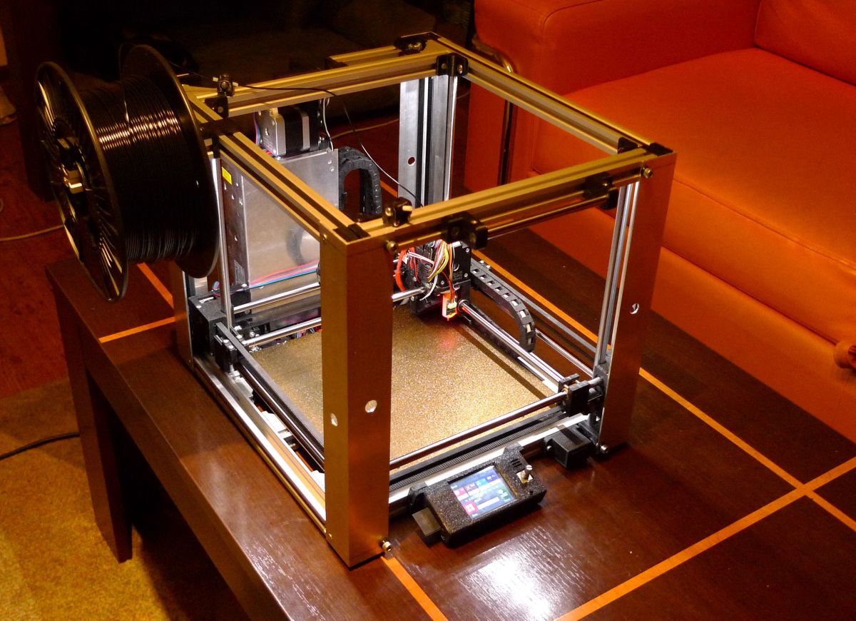
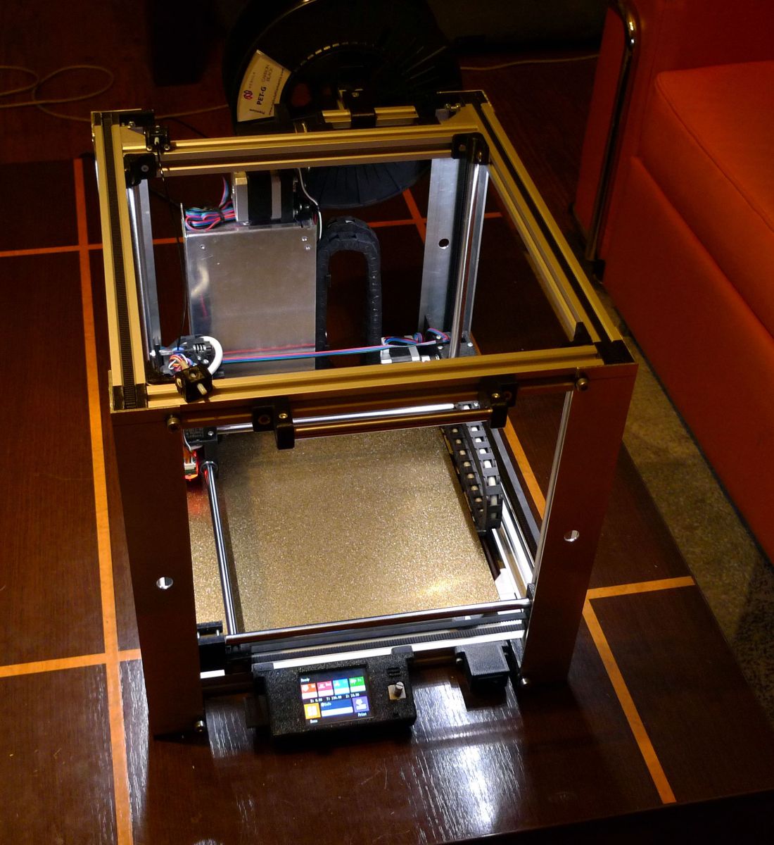
I would like to present you my latest work: DIY 3D printer, in what I think is a bit of a peculiar kinematics. I was inspired by the design of the Voron 0 printer, which I find elegant and simply pretty. I like the good use of the working volume and the practically lack of empty spaces in its volume. Core-XY kinematics, in turn, did not appeal to me so much, but somehow I was so charmed by the Ultimaker kinematics, so I decided to do it my way and marry these two ideas: perform the kinematics as in Ultimaker, while ensuring good use of volume, as in Voron 0

The project is constantly refined, some elements need finishing - sometimes I had to cut something after printing, melt it with a soldering iron, or make some unforeseen hole. But at the moment the printer is working and I am printing the next parts for my own needs with it.
Assumptions - Kinematics as in the Ultimaker: the extruder is located at the intersection of the X and Y axes. From the mechanical point of view, the X and Y axes are treated equally.
- The extruder and the entire XY mechanism also moves in the Z axis. The stage is permanently attached to the base.
- Possibly high printing speed.
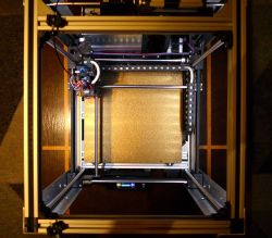
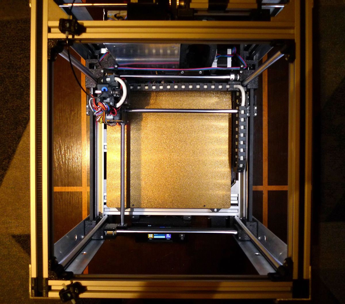
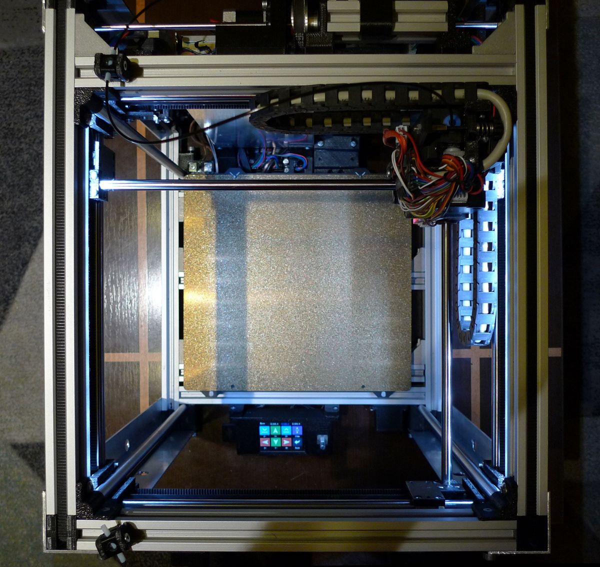
- Maximum use of the printer's outline, i.e. the best ratio of the working area to the volume of the printer.
- Guidance in the Z axis is carried out by a single motor based on belts.
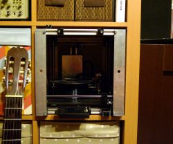
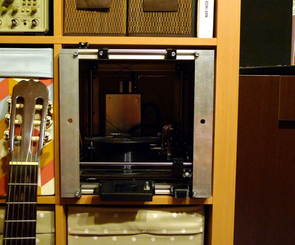
- The printer is to fit into the space of the Kallax (IKEA) bookcase.
- Working space about 20x20x20 cm.
- The table is magnetic from Prusy MK3
- Direct extruder with gear, silent stepsticks, table auto-levelling.
- Possibility of building.
- Easily accessible elements and the minimum required precision of workmanship.
- Elements printed from PET-G.
Design I made the project in FreeCad v.20 with the A2Plus add-on installed, which allows you to implement assemblies. I am not a professional - both 3D printing and 3D design are rather amateurs
The design is imperfect in terms of structure and dependencies, so it would be good to redo it. Well, for now, it is what it is - if there is interest in this project, I will improve it, or possibly leave it to someone who knows it better than me. It took me about a year and a half to create the project with a few longer breaks that resulted from discouragement or some problems along the way that went against my original ideas and clipped my wings a bit.
Dimensions - The working area is 20.5 x 19 x 22 cm (X/Y/Z)
- Printer size 32.5 x 32.5 x 38 mm (width / height / depth)
Execution - foreword As I mentioned, the design of the Voron 0 was a strong inspiration for me. Another nice printer, Voron 2, is based on the XY mechanism also moved in the Z axis (i.e. similar to this one) supported on belts.
Conclusions:
a) it is possible to realize the movement of the XY mechanism in the Z axis (and someone did it in a recognized project),
b) in the same project, the axle support was carried out on belts - so it does not have to be done on bolts.
However, the steering with 4 separate engines (as in Voron 2) seemed too overcomplicated to me. I found that one belt drive motor (16:60) should be enough for both precision and torque. In turn, the imperfections of setting the "zero" position can be eliminated using the table sensor.
Frame I made the frame based on V-SLOT 20x20 profiles (probably T-SLOT will also work, because the possibility of rolling rolls on the profile is not used here).
Precision is required for:
a) cutting the length of the V-SLOT profiles along the X axis (if the precision is not maintained, the rectangular frame will become a trapezoid),
b) perpendicularity of cutting V-SLOT profiles along the X axis (if the precision is not maintained, the rectangular frame will become a rhombus),
c) the position of the holes in the V-SLOT profiles along the Y axis (again, lack of precision means a trapezoid).
d) the same length of hardened rollers for the Z axis (the lack of equal length means unstable support for the printer, it may wobble when placed on a flat surface and there will be difficulty in initial positioning in the Z axis).
Point c), i.e. the precision of the holes, may not be required due to (ultimately) the use of angle bars connecting the profiles in the X axis with the profiles in the Y axis, which can be moved along the V-SLOT profiles in the Y axis and thanks to this, you can precisely adjust your distances. That is, perpendicularity is ensured by angles, and not by fastening the profiles "to the face". If angle brackets are used, it is then not necessary to make holes in the Y profiles to fix the X profiles. It's always less of a problem because there's less fixated reference. However, this optimization is still to be determined - I currently have both holes and angles.
In the Z axis, the connection between the frame elements is made using hardened bars with a diameter of 10 mm. The rods are attached to the corners of the V-SLOTs and pressed against them with elements made on a 3D printer. Originally, it seemed to me that such folding of the frame would be enough to maintain its stiffness, but the stiffness gains a lot after using additional profiles, angle bars 40x40x2 mm, in the corners of the printer. Angles in the corners make it difficult to access the adjustment elements for tensioning the belts, so that there was no need to dismantle them to adjust the belts, I drilled inspection holes in them.
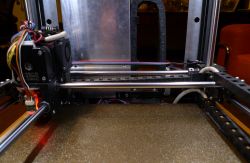
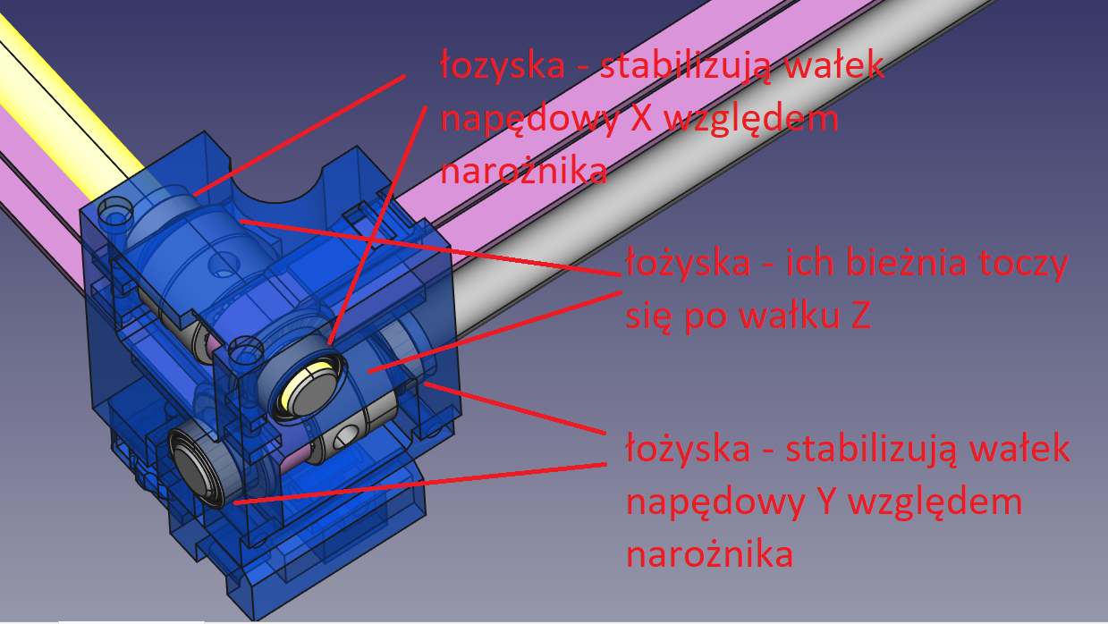
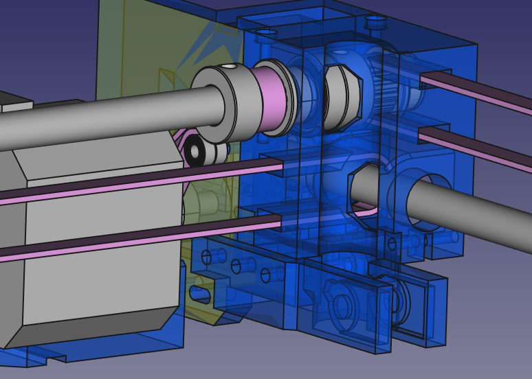
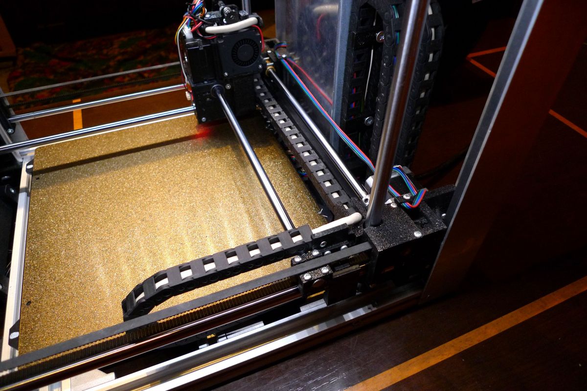
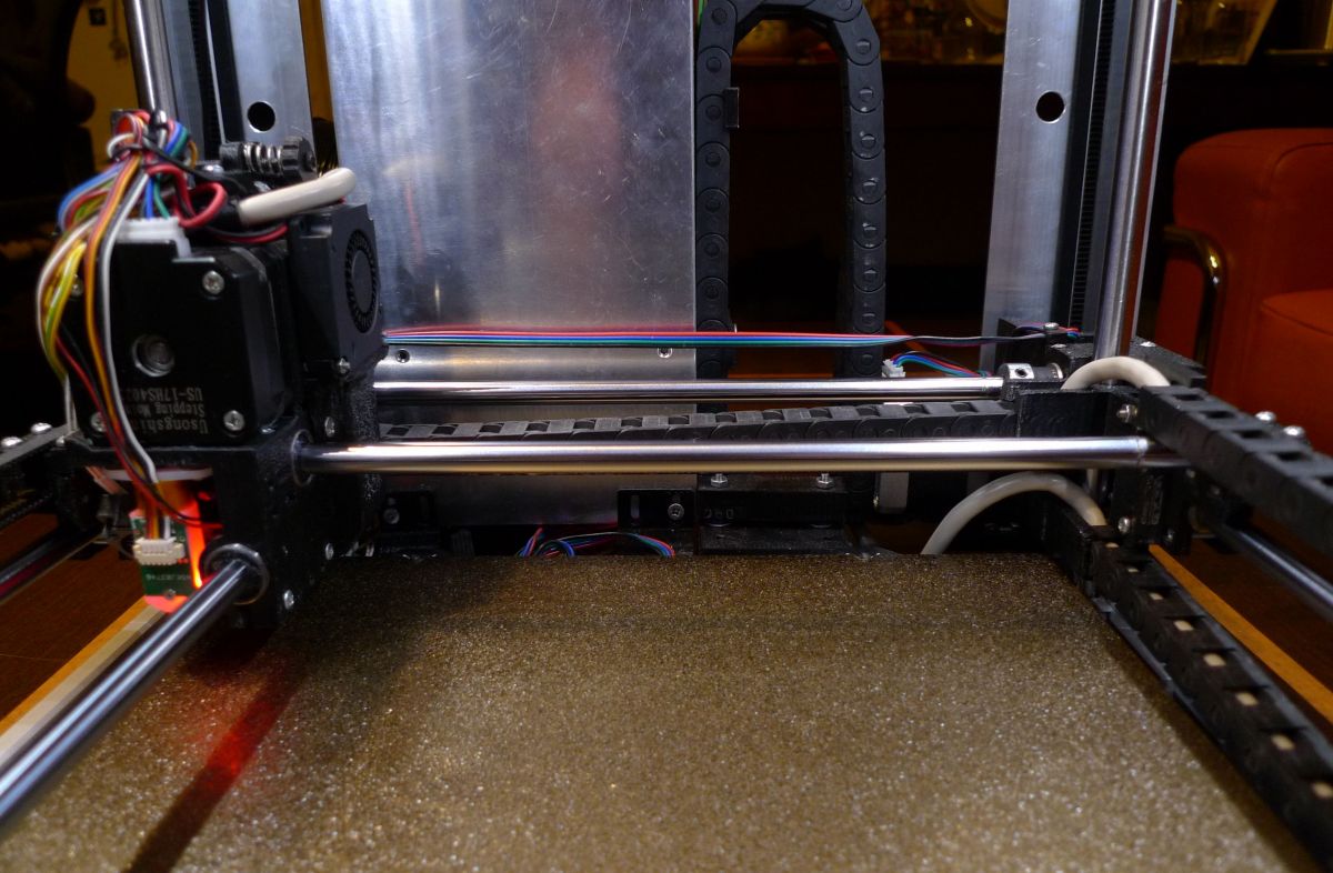
XY frame As in the Ultimaker, the drive shaft of the X and Y axes is also a rail on which the rods move, at the intersection of which the extruder is located. In the case of my printer, additional bearings are threaded on the drive shafts, the raceway (outer part of which) rolls on the rollers in the Z axis. This is one of my ideas
The whole thing does not fall apart, because the drive shafts fit into the appropriate bearings with a press fit, as well as (or rather primarily) because the drive belts forX and Y axes, when properly tensioned, pull the entire XY mechanism structure together and hold everything together. The rollers have a diameter of 8 mm.
XY frame - connectors in the corners 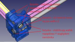
Similar corners are in each of the 4 corners.
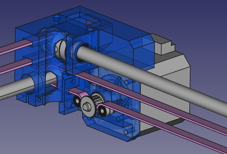
X drive 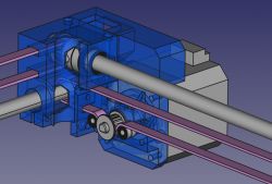
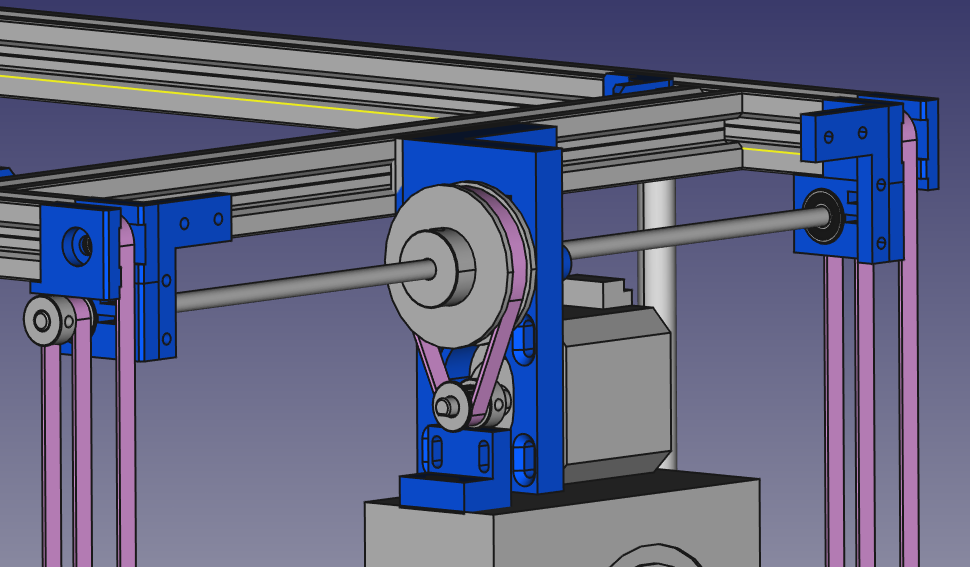
The X drive is carried out by means of a Nema17 motor, and the drive roller of the motor is properly wrapped by the belt with 3x7x3 mm bearings. This seems to be done correctly and the motor does not tend to skip on the belt or pick up slack. The problem I encountered in the first version of this printer is the unstable position of the motor relative to the X-axis drive shaft. Namely, as the entire X and Y mechanism moves in the Z-axis, there is no possibility of any additional fastening to the frame. The motor, when its shaft rotates, tries to move (turn) in the opposite direction according to the principle of action and reaction. Hence, the corner and the motor mount are printed with a solid allowance of material (to maintain its rigidity), while the stable position of the motor in relation to the X and Y drive shafts is ensured by appropriately (possibly) spaced bearings securing the shafts to the corner. This was one of the problems that nearly brought down the project in version one
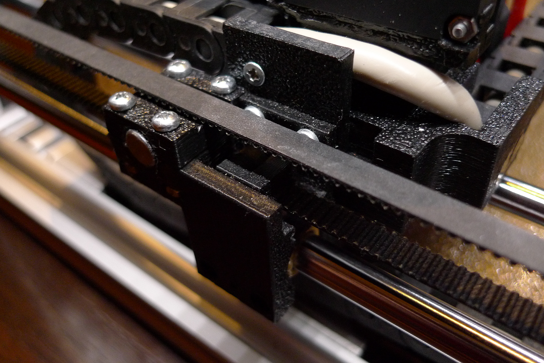
Belts are tensioned by a simple mechanism.
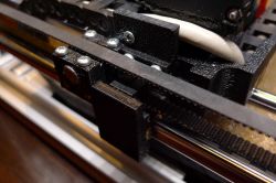 Y drive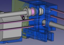
A similar problem with positional stability also affected the Y-axis drive motor. It now works flawlessly. The drive was transferred here using a belt loop and an additional roller.
Z drive I consider the drive in the Z axis to be one of the most interesting solutions from this printer
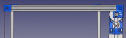

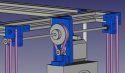
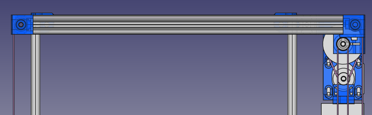
Each corner of the XY mechanism must be supported separately, but of course, when moving in the Z axis, they must move concurrently. At the same time, it is necessary to ensure the possibility of tensioning the belts as well as the possibility of pre-adjusting the "zero" position separately for all corners. I realized the drive in the Z axis using two GT2 belt loops. The strips fit the free space in the V-SLOT profiles, so I managed to integrate them into the frame and they do not take up additional space in the printer.
The way to adjust the Z axis is as follows:
1) Pre-position the frame, preferably after placing the printer on its side,
2) Tension the right and left belts (belt tensioning mechanisms are located in the front corners).
3) Then set the front corners relative to each other, take the table or the lower part of the frame as reference. Adjustments are made on the drive rollers of the Z axis.
4) Finally, adjust the position of the rear corners relative to the front ones.
It was quite easy for me to achieve an accuracy of 0.1 mm in the mutual position of the corners. I think that such precise corner setting is not necessary, because the final correction is provided by the BL-touch sensor and table positioning anyway.
Large belt loops have teeth on the outside, so in the corners I decided to use ordinary 5x14x5 mm bearings instead of dedicated (and too wide for me) drive rollers. The bearing is a little narrower than the width of the belt, but on the other hand, the movement in the Z axis is less intensive than in the X and Y axes. I think this will work in the long run.
Extruder I used a BMG clone as an extruder. As it has a gear, a smaller and lighter pancake motor can be used for the drive, which positively affects the speed of printing. Such an extruder works in my second printer and has not caused any problems for several years. The hotend is full-metal, so you can expect problems when printing with PLA. However, in my case, when assembling the hotend with attention, using paste and ensuring good cooling, I have no problem with it. The extruder moves on guide rollers using extended linear bearings LM8LUU.
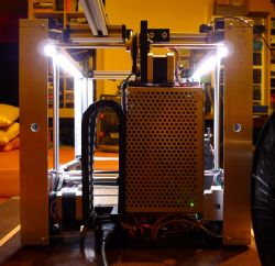
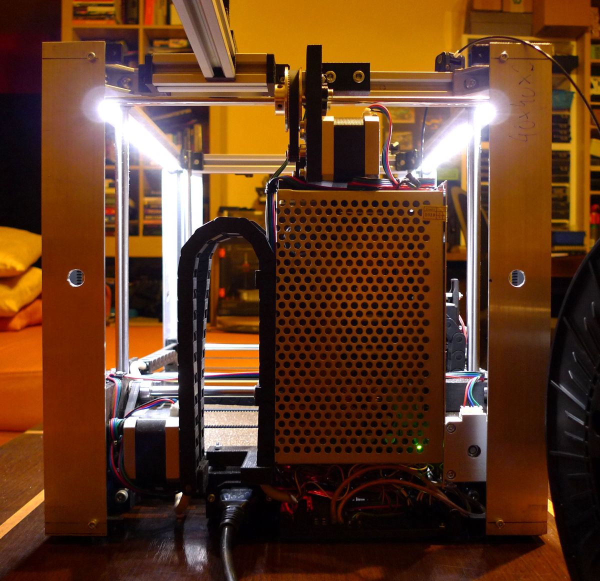
Electronics As the printer driver, I used the Bigtreetech SKR mini E3 board, which is placed in the space under the power supply. I compiled the soft for it using Visual Studio Code with the addition of PlatformIO. In turn, the role of the "control computer" is played by Bigtreetech TFT24. I have no complaints about this setup: it runs quietly, provides sensorless X/Y end-stops, and doesn't hang up.
Power supply and electricity management I power the printer with 24 V from a 200 W power supply. Its capacity is too small for reliable operation, so I will have to replace it with a 300 W power supply of similar dimensions.
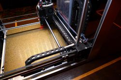
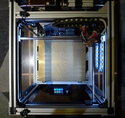
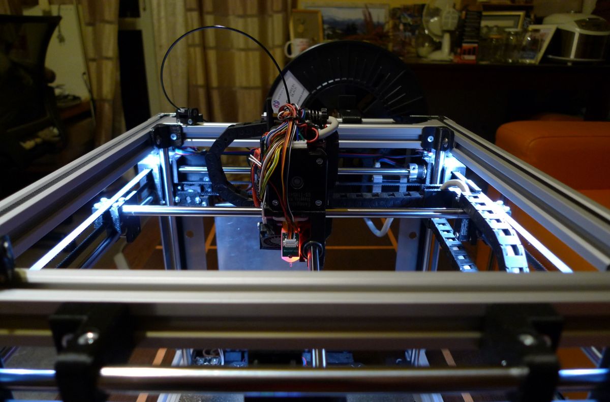
In order to transmit all signals to and from the extruder, I used a flexible cable with 16 wires with a cross-section of 0.14 mm^2. The flexibility of the cable is very important - in my case "Lap Kabel Stuttgart" worked well. The cross-section of the cable is sufficient to power the hotend with a supply voltage of 24 V. As you can see in the pictures, the cable is run in chains. I devoted a lot of attention to the proper guiding of the chains so that they do not take up too much of the working area of the printer and do not interfere with other elements of the printer.
I used 12V LED strips to illuminate the chamber - I connected two such strips in series. The size of these strips makes it easy to slide them into the space inside the V-SLOT profiles, although it is better to use strips that are not waterproof (they are not flooded with polyurethane) because they are easier to push into the profile.
To do My recent observation concerns insufficient blowing capacity. Currently, it is carried out by two centrifugal fans: one with dimensions of 30x30x10 mm is located between the nozzle and the BL-touch sensor, and the other, with dimensions of 40x40x10 mm, is located at the height of the extruder gearbox and conveys air through the tunnel to the vicinity of the nozzle. After the recent "Benchy" print, I conclude that the efficiency of this tandem is insufficient, as well as the air distribution around the nozzle is so-so - as the airflow is from the front and from the right, the print is less cooled from the rear and from the left. I need to look at both the efficiency of the fans and the nozzles directing the air around the hotend. I am a bit afraid of the performance of the fans, because I will not be able to integrate larger ones into the extruder without limiting the working area. Let's see - as I wrote, the printer is being refined all the time and I hope that I will be able to solve this problem as well :)
Another issue concerns the power supply to the Z axis motor. Namely, even though I have configured Marlin so that the Z axis power supply is always on, Marlin turns off this motor when the print is finished or interrupted. Of course, I searched for clues with the help of uncle Google, as well as on my own, and it seems to me that I have configured everything correctly, but after printing, the XY mechanism falls to the table. I don't think it's a serious problem, so I left it for later. As a last resort, you will need to configure the slicer to add a GCODE to the end of the printout, which will restore power to the Z axis motor, but I would prefer to avoid that.
As I mentioned, I will attach photos of the prints with the printing parameters to the article, so that you can view them and express your opinion. For now, however, I have to design a new air supply and that's what I'm focusing on.
Summary The project cost me a lot of nerves, and there were ups and downs along the way. The cost of all the elements exceeded PLN 2,000, and, as it happens in prototypes, many of them remained unused. The speed and quality of printing seem to be fine, later I will update the description with photos of prints with parameters. From the financial point of view, it is certainly better to buy a refined printer, e.g. Prusa MK3, assemble it calmly and consume a few jelly beans. But at the same time I can say that while constructing this contraption I learned something and gained faith in my abilities :)
Feel free to criticize and ask questions. I will also be grateful for suggestions and advice. I provide all design files and invite you to duplicate the design if you feel like it. I realize that the description is incomplete, I will update it on a regular basis.
Regards,
Fimek
Printer operation videos:
https://www.youtube.com/watch?v=a7SX1YrsGI8 https://www.youtube.com/watch?v=sZoe3s9C2s0 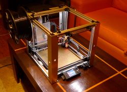







Comments
Congratulations on completing the project! Excellent imagination and talent for mechanics. [Read more]
Placed in place of the oven? :D a bit small but who needs it. Personally, I combine with a similar one with a working area of 40x40x40, if it works, 50x50 [Read more]
The printer is like a printer, the most important thing is missing, i.e. test prints showing the possibilities [Read more]
Wow, great job. I admire perseverance. I am a complete amateur in this topic, but the design looks professional. Congratulations on completing! [Read more]
The quality of the prints will be very dependent on the selection of parameters. Although I would have seen it at work and its effects myself :) [Read more]
The kinematics is called CrossXY ;) As for the chains, you'll be thinking about the umbilical cord in a moment, looking for a broken vein ;) Linear bearings don't like rotation very much. [Read more]
Hi, @maras52 I know they don't like it, that's why I have bearings only at the extruder, and the rollers don't rotate there. In turn, where they rotate (i.e. on the drive shafts) I used brass... [Read more]
By the way, you write that you used BMG, which in combination with NEMA17 is a terrible block by weight, look for a hextrudort with a 36STH20 engine (necessarily 20, 17 are weak) the author provides all... [Read more]
Well, the difference is significant, certainly worth considering. Is this motor still stepper or BLDC? If it's a stepper, it's like an evolution, but if you put a high-speed BLDC with a specific... [Read more]
Stepper ofkors ;) I will add that the factory engine weighed 177g ;) [Read more]
Congratulations on the project! Write to me for a small gift! :) [Read more]
Hi, In the end, I managed to make a fairly correct printout of the Bencha and the test cube. Only now I managed to finish the Bencha printout - earlier a few attempts ended in a fiasco, because when... [Read more]
Well, there's still a lot of work ahead of you It seems to you that it does not reach these speeds as you can see in the videos and after acceleration. You have a nice calculator here https://blog.prusa3d.com/pl/kalkulator-reprap_3416/... [Read more]
@jarzabek666 Well, I must admit that your post would be more informative for me (and in general anyway), i.e. if it was the so-called constructive criticism, and not just the criticism itself. I realize... [Read more]
Your acceleration is too small, so what you don't enter in the speed, it won't reach anyway For example for: Perimeters you have a speed of 100mm/s and an acceleration of 250mm/s2 it's... [Read more]
@jarzabek666 OK, thanks for the info, you're probably right. Recompiling Marlin is not a problem, so acceleration can be increased and check how it affects the printout. But what does this have to... [Read more]
You don't have to, it can be set in silker You've got the corners covered, just because of the acceleration. [Read more]
Hi, Thanks to my friend @jarzabek666 I made a lot of progress in starting the printer. Previously, I had a bad intuition, as it turned out that limiting the acceleration of the X/Y movement will result... [Read more]
Oh you see, and now I'm pecking the RF1000 with newer stuff :) It can only be done in silker, you have to specify that it should be sent for printing, not just calculate the printing time. In... [Read more]