Elektroda.com
Elektroda.com
X

FIMO DIY 3D printer, Ultimaker kinematics, Z axis mobile extruder

Fimek 2841 27
This content has been translated flag-pl » flag-en View the original version here.
  • FIMO DIY 3D printer, Ultimaker kinematics, Z axis mobile extruder
    Hi,

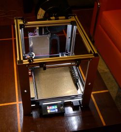
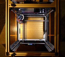
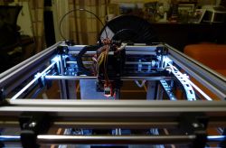
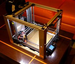
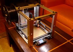
    I would like to present you my latest work: DIY 3D printer, in what I think is a bit of a peculiar kinematics. I was inspired by the design of the Voron 0 printer, which I find elegant and simply pretty. I like the good use of the working volume and the practically lack of empty spaces in its volume. Core-XY kinematics, in turn, did not appeal to me so much, but somehow I was so charmed by the Ultimaker kinematics, so I decided to do it my way and marry these two ideas: perform the kinematics as in Ultimaker, while ensuring good use of volume, as in Voron 0 :) The project is constantly refined, some elements need finishing - sometimes I had to cut something after printing, melt it with a soldering iron, or make some unforeseen hole. But at the moment the printer is working and I am printing the next parts for my own needs with it.

    Assumptions
    - Kinematics as in the Ultimaker: the extruder is located at the intersection of the X and Y axes. From the mechanical point of view, the X and Y axes are treated equally.
    - The extruder and the entire XY mechanism also moves in the Z axis. The stage is permanently attached to the base.
    - Possibly high printing speed.
    - Maximum use of the printer's outline, i.e. the best ratio of the working area to the volume of the printer.
    - Guidance in the Z axis is carried out by a single motor based on belts.
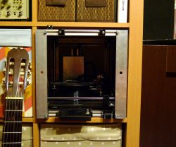
    - The printer is to fit into the space of the Kallax (IKEA) bookcase.
    - Working space about 20x20x20 cm.
    - The table is magnetic from Prusy MK3
    - Direct extruder with gear, silent stepsticks, table auto-levelling.
    - Possibility of building.
    - Easily accessible elements and the minimum required precision of workmanship.
    - Elements printed from PET-G.

    Design
    I made the project in FreeCad v.20 with the A2Plus add-on installed, which allows you to implement assemblies. I am not a professional - both 3D printing and 3D design are rather amateurs :) The design is imperfect in terms of structure and dependencies, so it would be good to redo it. Well, for now, it is what it is - if there is interest in this project, I will improve it, or possibly leave it to someone who knows it better than me. It took me about a year and a half to create the project with a few longer breaks that resulted from discouragement or some problems along the way that went against my original ideas and clipped my wings a bit.

    Dimensions
    - The working area is 20.5 x 19 x 22 cm (X/Y/Z)
    - Printer size 32.5 x 32.5 x 38 mm (width / height / depth)

    Execution - foreword
    As I mentioned, the design of the Voron 0 was a strong inspiration for me. Another nice printer, Voron 2, is based on the XY mechanism also moved in the Z axis (i.e. similar to this one) supported on belts.
    Conclusions:
    a) it is possible to realize the movement of the XY mechanism in the Z axis (and someone did it in a recognized project),
    b) in the same project, the axle support was carried out on belts - so it does not have to be done on bolts.
    However, the steering with 4 separate engines (as in Voron 2) seemed too overcomplicated to me. I found that one belt drive motor (16:60) should be enough for both precision and torque. In turn, the imperfections of setting the "zero" position can be eliminated using the table sensor.

    Frame
    I made the frame based on V-SLOT 20x20 profiles (probably T-SLOT will also work, because the possibility of rolling rolls on the profile is not used here).

    Precision is required for:
    a) cutting the length of the V-SLOT profiles along the X axis (if the precision is not maintained, the rectangular frame will become a trapezoid),
    b) perpendicularity of cutting V-SLOT profiles along the X axis (if the precision is not maintained, the rectangular frame will become a rhombus),
    c) the position of the holes in the V-SLOT profiles along the Y axis (again, lack of precision means a trapezoid).
    d) the same length of hardened rollers for the Z axis (the lack of equal length means unstable support for the printer, it may wobble when placed on a flat surface and there will be difficulty in initial positioning in the Z axis).

    Point c), i.e. the precision of the holes, may not be required due to (ultimately) the use of angle bars connecting the profiles in the X axis with the profiles in the Y axis, which can be moved along the V-SLOT profiles in the Y axis and thanks to this, you can precisely adjust your distances. That is, perpendicularity is ensured by angles, and not by fastening the profiles "to the face". If angle brackets are used, it is then not necessary to make holes in the Y profiles to fix the X profiles. It's always less of a problem because there's less fixated reference. However, this optimization is still to be determined - I currently have both holes and angles.

    In the Z axis, the connection between the frame elements is made using hardened bars with a diameter of 10 mm. The rods are attached to the corners of the V-SLOTs and pressed against them with elements made on a 3D printer. Originally, it seemed to me that such folding of the frame would be enough to maintain its stiffness, but the stiffness gains a lot after using additional profiles, angle bars 40x40x2 mm, in the corners of the printer. Angles in the corners make it difficult to access the adjustment elements for tensioning the belts, so that there was no need to dismantle them to adjust the belts, I drilled inspection holes in them.

    XY frame
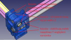
    As in the Ultimaker, the drive shaft of the X and Y axes is also a rail on which the rods move, at the intersection of which the extruder is located. In the case of my printer, additional bearings are threaded on the drive shafts, the raceway (outer part of which) rolls on the rollers in the Z axis. This is one of my ideas :) The whole thing does not fall apart, because the drive shafts fit into the appropriate bearings with a press fit, as well as (or rather primarily) because the drive belts forX and Y axes, when properly tensioned, pull the entire XY mechanism structure together and hold everything together. The rollers have a diameter of 8 mm.

    XY frame - connectors in the corners
    FIMO DIY 3D printer, Ultimaker kinematics, Z axis mobile extruder
    Similar corners are in each of the 4 corners.

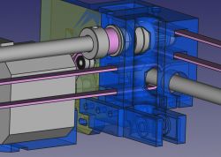
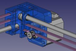
    X drive
    FIMO DIY 3D printer, Ultimaker kinematics, Z axis mobile extruder
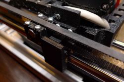
    The X drive is carried out by means of a Nema17 motor, and the drive roller of the motor is properly wrapped by the belt with 3x7x3 mm bearings. This seems to be done correctly and the motor does not tend to skip on the belt or pick up slack. The problem I encountered in the first version of this printer is the unstable position of the motor relative to the X-axis drive shaft. Namely, as the entire X and Y mechanism moves in the Z-axis, there is no possibility of any additional fastening to the frame. The motor, when its shaft rotates, tries to move (turn) in the opposite direction according to the principle of action and reaction. Hence, the corner and the motor mount are printed with a solid allowance of material (to maintain its rigidity), while the stable position of the motor in relation to the X and Y drive shafts is ensured by appropriately (possibly) spaced bearings securing the shafts to the corner. This was one of the problems that nearly brought down the project in version one :) Belts are tensioned by a simple mechanism.
    FIMO DIY 3D printer, Ultimaker kinematics, Z axis mobile extruder

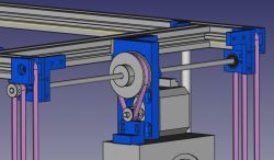
    Y drive
    FIMO DIY 3D printer, Ultimaker kinematics, Z axis mobile extruder
    A similar problem with positional stability also affected the Y-axis drive motor. It now works flawlessly. The drive was transferred here using a belt loop and an additional roller.

    Z drive
    I consider the drive in the Z axis to be one of the most interesting solutions from this printer :)
    FIMO DIY 3D printer, Ultimaker kinematics, Z axis mobile extruder FIMO DIY 3D printer, Ultimaker kinematics, Z axis mobile extruder FIMO DIY 3D printer, Ultimaker kinematics, Z axis mobile extruder
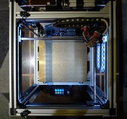
    Each corner of the XY mechanism must be supported separately, but of course, when moving in the Z axis, they must move concurrently. At the same time, it is necessary to ensure the possibility of tensioning the belts as well as the possibility of pre-adjusting the "zero" position separately for all corners. I realized the drive in the Z axis using two GT2 belt loops. The strips fit the free space in the V-SLOT profiles, so I managed to integrate them into the frame and they do not take up additional space in the printer.
    The way to adjust the Z axis is as follows:
    1) Pre-position the frame, preferably after placing the printer on its side,
    2) Tension the right and left belts (belt tensioning mechanisms are located in the front corners).
    3) Then set the front corners relative to each other, take the table or the lower part of the frame as reference. Adjustments are made on the drive rollers of the Z axis.
    4) Finally, adjust the position of the rear corners relative to the front ones.

    It was quite easy for me to achieve an accuracy of 0.1 mm in the mutual position of the corners. I think that such precise corner setting is not necessary, because the final correction is provided by the BL-touch sensor and table positioning anyway.

    Large belt loops have teeth on the outside, so in the corners I decided to use ordinary 5x14x5 mm bearings instead of dedicated (and too wide for me) drive rollers. The bearing is a little narrower than the width of the belt, but on the other hand, the movement in the Z axis is less intensive than in the X and Y axes. I think this will work in the long run.

    Extruder
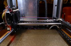
    I used a BMG clone as an extruder. As it has a gear, a smaller and lighter pancake motor can be used for the drive, which positively affects the speed of printing. Such an extruder works in my second printer and has not caused any problems for several years. The hotend is full-metal, so you can expect problems when printing with PLA. However, in my case, when assembling the hotend with attention, using paste and ensuring good cooling, I have no problem with it. The extruder moves on guide rollers using extended linear bearings LM8LUU.

    Electronics
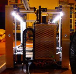
    As the printer driver, I used the Bigtreetech SKR mini E3 board, which is placed in the space under the power supply. I compiled the soft for it using Visual Studio Code with the addition of PlatformIO. In turn, the role of the "control computer" is played by Bigtreetech TFT24. I have no complaints about this setup: it runs quietly, provides sensorless X/Y end-stops, and doesn't hang up.

    Power supply and electricity management
    I power the printer with 24 V from a 200 W power supply. Its capacity is too small for reliable operation, so I will have to replace it with a 300 W power supply of similar dimensions.

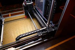
    In order to transmit all signals to and from the extruder, I used a flexible cable with 16 wires with a cross-section of 0.14 mm^2. The flexibility of the cable is very important - in my case "Lap Kabel Stuttgart" worked well. The cross-section of the cable is sufficient to power the hotend with a supply voltage of 24 V. As you can see in the pictures, the cable is run in chains. I devoted a lot of attention to the proper guiding of the chains so that they do not take up too much of the working area of the printer and do not interfere with other elements of the printer.

    I used 12V LED strips to illuminate the chamber - I connected two such strips in series. The size of these strips makes it easy to slide them into the space inside the V-SLOT profiles, although it is better to use strips that are not waterproof (they are not flooded with polyurethane) because they are easier to push into the profile.

    To do
    My recent observation concerns insufficient blowing capacity. Currently, it is carried out by two centrifugal fans: one with dimensions of 30x30x10 mm is located between the nozzle and the BL-touch sensor, and the other, with dimensions of 40x40x10 mm, is located at the height of the extruder gearbox and conveys air through the tunnel to the vicinity of the nozzle. After the recent "Benchy" print, I conclude that the efficiency of this tandem is insufficient, as well as the air distribution around the nozzle is so-so - as the airflow is from the front and from the right, the print is less cooled from the rear and from the left. I need to look at both the efficiency of the fans and the nozzles directing the air around the hotend. I am a bit afraid of the performance of the fans, because I will not be able to integrate larger ones into the extruder without limiting the working area. Let's see - as I wrote, the printer is being refined all the time and I hope that I will be able to solve this problem as well :)

    Another issue concerns the power supply to the Z axis motor. Namely, even though I have configured Marlin so that the Z axis power supply is always on, Marlin turns off this motor when the print is finished or interrupted. Of course, I searched for clues with the help of uncle Google, as well as on my own, and it seems to me that I have configured everything correctly, but after printing, the XY mechanism falls to the table. I don't think it's a serious problem, so I left it for later. As a last resort, you will need to configure the slicer to add a GCODE to the end of the printout, which will restore power to the Z axis motor, but I would prefer to avoid that.

    As I mentioned, I will attach photos of the prints with the printing parameters to the article, so that you can view them and express your opinion. For now, however, I have to design a new air supply and that's what I'm focusing on.

    Summary
    The project cost me a lot of nerves, and there were ups and downs along the way. The cost of all the elements exceeded PLN 2,000, and, as it happens in prototypes, many of them remained unused. The speed and quality of printing seem to be fine, later I will update the description with photos of prints with parameters. From the financial point of view, it is certainly better to buy a refined printer, e.g. Prusa MK3, assemble it calmly and consume a few jelly beans. But at the same time I can say that while constructing this contraption I learned something and gained faith in my abilities :)

    Feel free to criticize and ask questions. I will also be grateful for suggestions and advice. I provide all design files and invite you to duplicate the design if you feel like it. I realize that the description is incomplete, I will update it on a regular basis.

    Regards,
    Fimek


    Printer operation videos:

    https://www.youtube.com/watch?v=a7SX1YrsGI8
    https://www.youtube.com/watch?v=sZoe3s9C2s0
    FIMO DIY 3D printer, Ultimaker kinematics, Z axis mobile extruder FIMO DIY 3D printer, Ultimaker kinematics, Z axis mobile extruder FIMO DIY 3D printer, Ultimaker kinematics, Z axis mobile extruder FIMO DIY 3D printer, Ultimaker kinematics, Z axis mobile extruder
    FIMO DIY 3D printer, Ultimaker kinematics, Z axis mobile extruder FIMO DIY 3D printer, Ultimaker kinematics, Z axis mobile extruder FIMO DIY 3D printer, Ultimaker kinematics, Z axis mobile extruder FIMO DIY 3D printer, Ultimaker kinematics, Z axis mobile extruder
    FIMO DIY 3D printer, Ultimaker kinematics, Z axis mobile extruder

    Cool? Ranking DIY
    About Author
    Fimek
    Level 15  
    Offline 
    Fimek wrote 196 posts with rating 273, helped 3 times. Been with us since 2003 year.
  • #2
    doktorpyta
    Level 11  
    Congratulations on completing the project!
    Excellent imagination and talent for mechanics.
  • #3
    chemik_16
    Level 25  
    Placed in place of the oven? :D

    a bit small but who needs it.
    Personally, I combine with a similar one with a working area of 40x40x40, if it works, 50x50
  • #4
    Jarzabek666
    Level 38  
    The printer is like a printer, the most important thing is missing, i.e. test prints showing the possibilities
  • #5
    kowalczukkn
    Level 3  
    Wow, great job. I admire perseverance. I am a complete amateur in this topic, but the design looks professional. Congratulations on completing!
  • #6
    LA72
    Level 41  
    Jarzabek666 wrote:
    The printer is like a printer, the most important thing is missing, i.e. test prints showing the possibilities


    The quality of the prints will be very dependent on the selection of parameters.
    Although I would have seen it at work and its effects myself :)
  • #7
    maras52
    Level 14  
    The kinematics is called CrossXY ;) As for the chains, you'll be thinking about the umbilical cord in a moment, looking for a broken vein ;) Linear bearings don't like rotation very much.
  • #8
    Fimek
    Level 15  
    Hi,

    @maras52 I know they don't like it, that's why I have bearings only at the extruder, and the rollers don't rotate there. In turn, where they rotate (i.e. on the drive shafts) I used brass bushings. Regarding the naming - something I felt like this must have a name :)

    @doktorpyta @kowalczukkn thanks for the kind word :)

    @Jarzabek666 so far I have a printout of the test cube and a few things that are already working in this printer. The print of the "benchy" ship came out poorly on this less cooled side. When I eliminate the problem with cooling (I hope it will work ...), I will add a photo of the test print.

    Regards,
    Fimek
  • #9
    maras52
    Level 14  
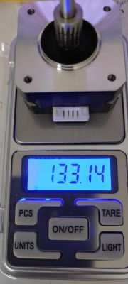
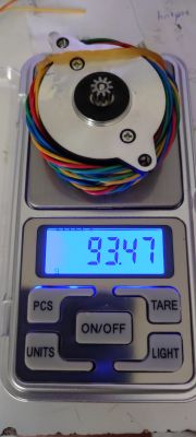
    By the way, you write that you used BMG, which in combination with NEMA17 is a terrible block by weight, look for a hextrudort with a 36STH20 engine (necessarily 20, 17 are weak) the author provides all kinds of "hulls" for various hotbeds from V6 to Dragons ;)

    You have a weight comparison of a pancake and a 36:
    FIMO DIY 3D printer, Ultimaker kinematics, Z axis mobile extruder FIMO DIY 3D printer, Ultimaker kinematics, Z axis mobile extruder
  • #10
    Fimek
    Level 15  
    Well, the difference is significant, certainly worth considering. Is this motor still stepper or BLDC? If it's a stepper, it's like an evolution, but if you put a high-speed BLDC with a specific gear there, you could really make the extruder significantly lighter, but it would require modification of the electronics (of course, it would be a bit of a hassle). Hmm...... :)
  • #11
    maras52
    Level 14  
    Stepper ofkors ;) I will add that the factory engine weighed 177g ;)
  • #12
    gulson
    System Administrator
    Congratulations on the project! Write to me for a small gift! :)
  • #13
    Fimek
    Level 15  
    Hi,

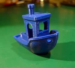
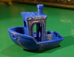
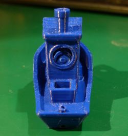
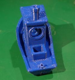
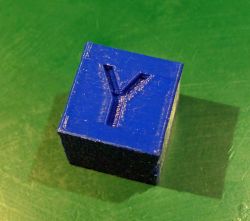
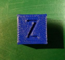
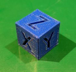
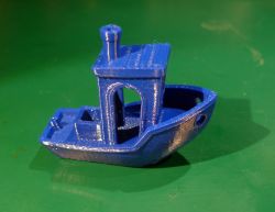
    In the end, I managed to make a fairly correct printout of the Bencha and the test cube. Only now I managed to finish the Bencha printout - earlier a few attempts ended in a fiasco, because when the printer started printing overhangs (at the top of the windows), at some point the nozzle hooked on the overhang and detached the printout from the bed. It turned out that there were two problems:
    - Inefficient airflow, first because of my poor design, and then, after I improved the design, because of the poor efficiency of the fans. The currently installed 4010 ball bearing centrifugal fans are OK.
    - The shape of the nozzle - the previous one was too sharply cut. The chamfer formed a large plane around the nozzle outlet. As a test, I replaced the nozzle with a newly purchased one, which looks more like a triangle in profile, and it's OK, you can't hear the nozzle hooking on the printout.

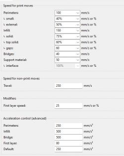
    The printout was quite fast (the parameters are attached in the picture, a screenshot from the Slic3r program). I printed with PET-G from Nebula (a nice and really reliable filament).

    To improve:
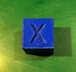
    - There is some visible interdependence between the movement of the extruder in the X and Y axes, which I want to eliminate. This can be seen in the form of bulges on the edges of the test cube and in the form of a rounded interior in a rectangular shape (trough) below the line of the back window of the Benchy and in the form of a rounded letter Z on the test cube. Probably the printing parameters also have a role here, but the correlation (minimal, but visible) was noticeable when manually moving the extruder along the X axis, and then Y (where the movement in the Y axis, which followed the movement in X, caused a slight shift also in the axis X - and vice versa). Maybe it's a matter of friction on the guide bushings, or maybe the X and Y motors wobble slightly on their mounting points. I did not register this swing earlier, but there is some reason for this interdependence - so it needs to be checked and eliminated.
    - I need to fine-tune the printing parameters, because the seam is visible and looks bad. It seems to me that here the mechanism of the printer is less important, and more important - the material and printing parameters.

    I am attaching Benchy printing videos and pictures of the prints. Regards :)

    https://youtu.be/DnT7nxemFZc
    https://youtu.be/KUBd8TYOLXg

    FIMO DIY 3D printer, Ultimaker kinematics, Z axis mobile extruder
    FIMO DIY 3D printer, Ultimaker kinematics, Z axis mobile extruder FIMO DIY 3D printer, Ultimaker kinematics, Z axis mobile extruder FIMO DIY 3D printer, Ultimaker kinematics, Z axis mobile extruder FIMO DIY 3D printer, Ultimaker kinematics, Z axis mobile extruder FIMO DIY 3D printer, Ultimaker kinematics, Z axis mobile extruder FIMO DIY 3D printer, Ultimaker kinematics, Z axis mobile extruder FIMO DIY 3D printer, Ultimaker kinematics, Z axis mobile extruder FIMO DIY 3D printer, Ultimaker kinematics, Z axis mobile extruder FIMO DIY 3D printer, Ultimaker kinematics, Z axis mobile extruder
  • #14
    Jarzabek666
    Level 38  
    Well, there's still a lot of work ahead of you

    Fimek wrote:
    The printout was quite fast (the parameters are attached in the picture, a screenshot from the Slic3r program)


    It seems to you that it does not reach these speeds as you can see in the videos and after acceleration.

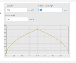
    You have a nice calculator here https://blog.prusa3d.com/pl/kalkulator-reprap_3416/ so it's not like I took it out of my ass, I just threw what you have and it barely reaches 80mm/s at peak.
  • #15
    Fimek
    Level 15  
    @Jarzabek666 Well, I must admit that your post would be more informative for me (and in general anyway), i.e. if it was the so-called constructive criticism, and not just the criticism itself.

    I realize that there is still a lot to do here - I write about everything without coloring. Nevertheless, I think that my idea for this printer has potential, but as I am a total amateur when it comes to 3D printing, mechanics and CAD, I'm getting tired of it, slowly removing imperfections and treating it as a hobby. And yes, despite the still imperfect results, I am happy that I was able to build what you see here in real life.

    I can print the cube at a higher speed, it's not a problem and I'm convinced that it will come out no worse than in the pictures. But at the moment it doesn't make sense, because I have a feeling that the degradation of quality is caused by the interdependence I mentioned, which I want to eliminate and which I wrote about. There are probably other problems, but I will eliminate them one by one.

    Regards,
    Fimek
  • #16
    Jarzabek666
    Level 38  
    Your acceleration is too small, so what you don't enter in the speed, it won't reach anyway

    For example for:

    Perimeters you have a speed of 100mm/s and an acceleration of 250mm/s2 it's peak only when you print a line longer than 5cm you get this speed below like a 20x20mm cube you only get a peak of 70mm/s almost half of what you think.

    FIMO DIY 3D printer, Ultimaker kinematics, Z axis mobile extruder

    You should have high accelerations as long as the printer can handle around 3000mm/s2
  • #17
    Fimek
    Level 15  
    @Jarzabek666 OK, thanks for the info, you're probably right. Recompiling Marlin is not a problem, so acceleration can be increased and check how it affects the printout. But what does this have to do with the problems I wrote about in previous posts?
  • #18
    Jarzabek666
    Level 38  
    Fimek wrote:
    Recompiling Marlin is not a problem at all


    You don't have to, it can be set in silker

    Fimek wrote:
    But what does this have to do with the problems I wrote about in previous posts?


    You've got the corners covered, just because of the acceleration.
  • #19
    Fimek
    Level 15  
    Hi,

    Thanks to my friend @Jarzabek666 I made a lot of progress in starting the printer. Previously, I had a bad intuition, as it turned out that limiting the acceleration of the X/Y movement will result in a printout with less artifacts. I was wrong :) As I understand now how Marlin works: the introduction of a limitation on the acceleration of movement does not go hand in hand with what the extruder releases. I was convinced that the movements of the head and the work of the extruder are synchronized. Yes, I know that the filament compresses and this effect can be compensated for, but I don't really buy it, because there is no room for compression in the direct extruder, and the melted filament is incompressible. I can only see the possible inaccuracy of the stepper motor, which introduces its errors (because it is asynchronous). Unless it's about the asynchronous operation of the motor + additionally expanding (or just reducing the volume?) of the filament while melting it. But that's probably a topic for another discussion :)

    returning:
    - the introduction of the acceleration limiter reduces "mechanical" artifacts such as snake skin on the surface and reduces noise, but causes artifacts such as dripping on the corners. Well, but reducing the acceleration is necessary, because at some point the printer will stop "kneading" and, for example, shake and lose steps.
    - in turn, the introduction of linear advance compensates for the effects caused by the software acceleration limitation.

    I started with an acceleration of 500 mm/s^2, which, as my colleague @Jarzabek666 rightly pointed out, causes the head to accelerate for a long time and the printout has no chance to reach the speed of 100 mm/s. With such acceleration I got nice effects of linear advance for the coefficient k = 0.1 ... 0.12.

    Then I started playing with the acceleration and experimentally came up with 2000 mm/s^2 for X/Y and 200 mm/s^2 for the Z axis. For a randomly set acceleration of 10000 mm/s^2 I had step loss. For an acceleration of 2000 mm/s^2, the optimal k factor was 0.025 for me.

    My conclusions so far:
    - acceleration in the Z axis improved the appearance of the seam,
    - acceleration in the X/Y axes paradoxically reduced the amount of artifacts, which was the biggest shock for me :) Goosebumps (wobbling) problems have started to emerge, and here we will continue to play with speeding up and optimizing. For now, I can write that the current printer is actually about 2x faster than my previous printer, the converted Renkforce RF100, the adventures with which I described in one of the threads on the electrode.

    One more note: in the case of my SKR mini + Bigtreetech TFT 2.4 tiles, the acceleration settings, neither resulting from Marlin settings, nor selected in Slicer, matter. TFT always "wins" and you have to enter these values with your finger on its screen, because they will dominate the printer's work anyway.

    Regards!
  • #20
    Jarzabek666
    Level 38  
    Oh you see, and now I'm pecking the RF1000 with newer stuff :)

    Fimek wrote:
    One more note: in the case of my SKR mini + Bigtreetech TFT 2.4 tiles, the acceleration settings, neither resulting from the Marlin settings, nor selected in Slicer, do not matter


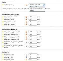
    It can only be done in silker, you have to specify that it should be sent for printing, not just calculate the printing time.

    In PS I have this and it works

    FIMO DIY 3D printer, Ultimaker kinematics, Z axis mobile extruder
  • #22
    TWl
    Level 21  
    Well, well, I rarely write here lately, but Fimku, I tip my hat :-) Greetings also to Dr. P!

    T
  • #23
    sakitume
    Level 2  
    Fimek, well done! This is an amazing project. I learned about it from your YouTube videos about it.
    I've made several CoreXY machines over the years but never a CroXY. I really like what you've done here and am very interested in building a machine using your design. Thanks for sharing this project.
    I am using Google translate to read this message thread as my native language is English. I'm sorry that I cannot communicate in Polish. I hope you are able to understand what I'm writing.
    Please reply and let me know if you wouldn't mind me asking more questions about this printer in English. Or if I should use Google translate to try and convert my English to Polish first. Thank you
  • #24
    Fimek
    Level 15  
    Hello,

    I'm pleased that you enjoy this project, and it would be my pleasure if you decided to replicate it :) I can communicate in English. I'll do my best to clarify any questions you have about the printer. However, I want to make you aware that the project is currently messy. Considering its current state, it would be best to begin with understanding the operational principles and addressing some of the issues I've encountered. In the meantime, I will work on cleaning up the project to ensure consistency and proper dependencies, making replication of the printer easier. I've got a plan to have a description of the printer written in English anyway, but it will take time. Certainly you can start with the project "as is" (project files are attached to the opening post) but as the printer is yet in "alpha" state, you would need to fix problems you will encounter on your own. Does this plan sound good to you?

    Cheers!
    Fimek
  • #25
    sakitume
    Level 2  
    Thanks for replying. Yes, that plan sounds perfect. I do not expect a how-to or a step-by-step instruction manual. My intent is to understand how you designed and built this and build something similar based on what you've done. There is a good chance I will make modifications as I go along to match the parts that I have (or can obtain). I am also interested in using Klipper firmware instead of Marlin

    I usually make numerous test prints and assemblies when I play with a project like this as I enjoy this process. For example I may want to build just the X/Y motion system in a test harness without worrying about having a toolhead or any movement along Z. This way I can become familiar with how the system operates and if I may want to make adjustments.

    If you don't mind I would like to post to a few different Discord servers (about 3D printers) about your printer and point them to your YouTube videos.
  • #26
    Fimek
    Level 15  
    Hello!

    I don't mind spreading the information about this printer over Discord. Speaking of a discussion about this project, let me know via private message, or if you think it would be beneficial for the readers, we can have it in a public place (like here). I'm also a Discord user, but so far, I haven't used it much. However, that might change if you invite me to the place where project-related activities are taking place :) Just please don't expect too much from me – I'm a hobbyist and my intuition might have failed somewhere.

    Can say more about your projects? Your approach to designing sounds very interesting :)

    Cheers!
  • #27
    sakitume
    Level 2  
    Hello Fimek,

    I've recently gotten back to building/experimenting with 3D printers (since around April). I've found a few Discord servers where I listen and or have shared about my projects. Since then I've completed about three CoreXY printers and have made numerous experiments in between. I've posted about some of them in the "Delayed Development" discord server. Here is an invite:
    https://discord.gg/2ZSmyrRF2h

    I hope you consider joining or invite me to another similar Discord where we can discuss and possibly have others join in.

    Here is a link to a channel about my "BBox 180" project on that server:
    https://discord.com/channels/1085579502735872044/1119417214915842258/1119446600402604084

    Here is a link to a post where I provide an example of my experimental/prototype process:
    https://discord.com/channels/1085579502735872044/1117003893340123136/1117003893340123136

    Here is a video about my BBox prototype: https://www.youtube.com/watch?v=T7EcTlZo50s&t=8s