Elektroda.com
Elektroda.com
X
This content has been translated flag-pl » flag-en View the original version here.
  • Egg - printer (Easter egg printer)

    Hello,

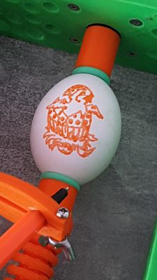
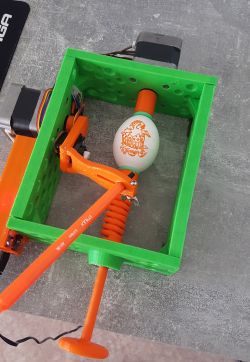
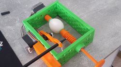
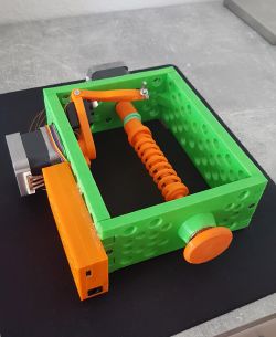
    as Christmas is fast approaching, I would like to present you an egg printer (in the sense of Easter eggs :wink: ) that I recently launched. This is one of those unnecessary projects, but that's where fun counts :D

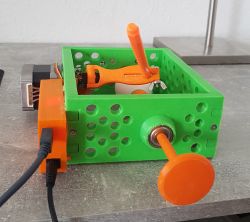
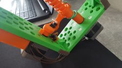
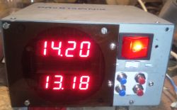
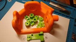
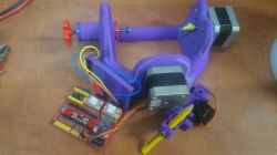
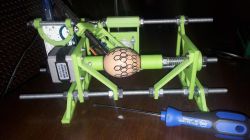
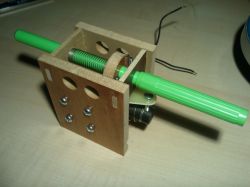
    I designed all the necessary elements of the structure in SketchUp and printed it on a 3d printer. Green from ABS, orange from PLA. Unfortunately, I do not know for what reasons, but I struggled with designing the electronics housing and it is a good centimeter too big. I did not want to change anymore and I left it like that :please:
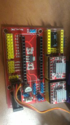
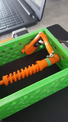
    The driver is an Arduino nano with GRBL software loaded, for this A4988 stepper motor drivers and recovered motors. They could be much smaller and weaker, but that's what I had. The pen is controlled by a micro servo, and the limit switch is a slotted optocoupler (also from the drawer).

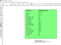
    The use of a servo carries a slight inconvenience, or two. First, you need to modify the GRBL library by uploading a servo instruction file. Secondly, each time you generate a Gcode file, you need to process the file again. The postprocessor converts the commands to raise and lower the pen. Everything is described quite nicely HERE .

    There is actually nothing to write too much about here. If you need more details, please ask in the comments.

    Summing up the project, it is admittedly a bit too early for me to wish you a happy "Hallelujah".

    Below are some videos and photos:
    Egg - printer (Easter egg printer) Egg - printer (Easter egg printer) Egg - printer (Easter egg printer) Egg - printer (Easter egg printer)
    Egg - printer (Easter egg printer) Egg - printer (Easter egg printer) Egg - printer (Easter egg printer)

    I don't have any sensible video editing program so I have no way to speed up videos. So I suggest you click on the settings immediately and increase the playback speed.


    Cool? Ranking DIY
    Do you have a problem with Arduino? Ask question. Visit our forum Arduino.
    About Author
    .:KoSik:.
    Level 18  
    Offline 
    .:KoSik:. wrote 596 posts with rating 271, helped 19 times. Live in city Frankfurt nad Menem. Been with us since 2006 year.
  • #2
    Anonymous
    Anonymous  
  • #3
    tplewa
    Level 39  
    He he ;) I can see that I am not alone ;) I myself came up with the idea to do something like that for my daughter ;) However, I partially rely on the finished Sphere-O-bot project:

    https://www.thingiverse.com/thing:1683764

    https://www.jjrobots.com/sphere-o-bot-jjrobots-version/

    Specifically, it probably turned out that the frame because the suction cup holders have to be designed different (unfortunately ordered from China do not fit this project), and a few other replacements - in total, for the elements that I have in stock (because the ready-made elements from the project do not fit very well) and maybe some other small fixes (e.g. bearings in drawing arm) ...

    At the moment, the printed frame:

    Egg - printer (Easter egg printer)

    ... the second one in red is currently in the printing phase (about 55% after less than 10 hours of printing).

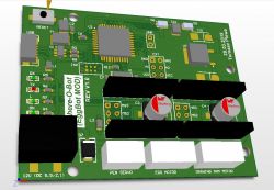
    The original uses as electronics Arduino Leonardo + JJrobots´s Brain SHIELD (https://www.jjrobots.com/product/b-robot-electronic-brain-shield/)

    Unfortunately, I do not have any arduino board in stock, and the purchase + execution of the shield was a bit pointless, I found that I would stuff it on one PCB.
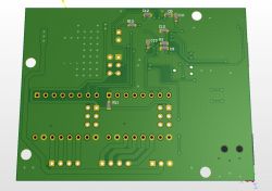
    Initially, the A4988 stepsticks were supposed to be on the PCB - but looking at the price of the A4988 chip at TME (PLN 16.65) I gave the sockets because I have some stepsticks at home for this, the purchase of a ready A4988 on a well-known auction portal is 1/2 the price of the chip at TME. .. RC components mostly size 0603, connectors for JST motors XH ... series PCB two layers ...

    Egg - printer (Easter egg printer)

    Egg - printer (Easter egg printer)

    The board should be like arduino, "although it will come out in the wash" because I was based on the dimensions of the Internet, I am not entirely sure about the position of the power connector and micro USB (but this is probably the smallest problem).

    As a chip, I chose the ATMega32U4, which is compatible with the original one used in the Leonardo project, and a compromise, and the original FTDI for an additional cost (I wanted to avoid Chinese counterfeits and converters for which Windows 10 does not have the original drivers) ... In fact, the whole thing should be compatible with Arduino.
    Initially, the project was supposed to be on some STM32 which I have some in stock, but unfortunately I am afraid that due to the multitude of other work, I would not be able to create software by Christmas ...

    The diagram and gerberas in the attachment may be useful to someone ... The tiles have just gone into production, so the system has not yet been tested ;)

    Sorry for sticking to the topic this way ;) but there is no point in setting up a thread about an unfinished project yet, and here probably interested people will come, so maybe someone will benefit from something ;)
  • #4
    .:KoSik:.
    Level 18  
    Hydrantx wrote:
    How did you solve the problem of getting to the surface of the egg?

    The arm drops under its own weight, as seen in the movies. The servo arm is a bit trimmed, because it happened that it threw the pen too hard and it didn't drop anymore. It's okay now.

    Hydrantx wrote:
    He also wrote and made available a Windows program for it, where only a graphic file was uploaded, and the rest works by itself

    G-code is very fun to generate with Inkscape. There are many options and settings so there is something for everyone. After generating the file, it takes a few seconds for the postprocessor to process it, so it's not a big deal and it's probably not worth wasting time looking for another solution. If I had to use it every day, I would probably try to automate this process, but in this case it can get over it.

    Added after 3 [minutes]:

    tplewa wrote:
    He he I see I'm not alone


    Even the colors are the same :lol:
  • #5
    tplewa
    Level 39  
    .:KoSik:. wrote:

    tplewa wrote:
    He he I see I'm not alone


    Even the colors are the same :lol:


    He he colors as in the Sphere-O-Bot project ;) but only one piece, because the orange filament will not be enough for the next frame, so the red one is printed (it will be for a gift in the family because it was not profitable to order less than 4 PCBs). As for the filament, basically all the elements from PETG Spectrum ... I probably sit down to CAD right now and design what else is needed for this project, because with the deadline I can barely fit before Christmas - that's how a man does something on last minute ;)
  • #6
    And!
    Admin of Design group
    Cool design, how is ABS plastic different from PLA?
    Perhaps replacing the servo with an electromagnet would speed up the printout?
  • #7
    .:KoSik:.
    Level 18  
    And! wrote:
    Cool design, how is ABS plastic different from PLA?


    In a nutshell (differences):
    ABS - hard, strong
    PLA - soft, flexible

    And! wrote:
    Perhaps replacing the servo with an electromagnet would speed up the printout?

    There is no need. You can go ahead and speed it up, but the pen does not make it. Anyway, what fun it is when the printout ends after a minute :roll:
  • #8
    wirusa
    Level 13  
    Could a colleague describe the uploading process to Arduino, and then editing the drawing, step by step, providing links?
  • #10
    tplewa
    Level 39  
    wirusa wrote:
    Could a colleague describe the uploading process to Arduino, and then editing the drawing, step by step, providing links?


    As a colleague, he is interested in something like that and asks such a question ;) then I suggest you take interest in the sphere-o-bot project or similar. The software for Arduino compatible in these projects is with eggbot - it prints directly from Inscape (using the appropriate plug-in) and you do not need to play with gcode etc. I chose this option because my daughter would have easier fun, i.e. draw, click, print ;)

    here is the description:
    https://wiki.evilmadscientist.com/Installing_software

    As for the firmware for Arduino here:
    https://github.com/plex3r/EggDuino

    The original EggBot on the PIC here:
    https://github.com/evil-mad/EggBot

    Inscape Extension:
    https://github.com/plex3r/plotink

    All in all, by entering eggbot in google you will find a lot and you do not necessarily need a 3d printer to do it. People make of various materials (wood, dibond, etc.)
  • #11
    .:KoSik:.
    Level 18  
    tplewa wrote:
    actually prints directly from Inscape


    For me it is also not overly complicated. It comes down to a few clicks. G-codes don't hurt :sm31: but of course the easier the better.
  • #12
    Puzli
    Level 10  
    .:KoSik:. wrote:
    And! wrote:
    Cool design, how is ABS plastic different from PLA?


    In a nutshell (differences):
    ABS - hard, strong
    PLA - soft, flexible


    A small bug has crept in
    ABS - high strength, higher flexibility than PLA, better temperature resistance, soft / easy to process.
    PLA - high hardness, limited flexibility, good durability but less than ABS
  • #13
    tplewa
    Level 39  
    Puzli wrote:
    .:KoSik:. wrote:
    And! wrote:
    Cool design, how is ABS plastic different from PLA?


    In a nutshell (differences):
    ABS - hard, strong
    PLA - soft, flexible


    A small bug has crept in
    ABS - high strength, higher flexibility than PLA, better temperature resistance, soft / easy to process.
    PLA - high hardness, limited flexibility, good durability but less than ABS


    It is all very relative ;) For example, ABS with thin walls is very weak, another question what is meant by strength? Whether for bend or stroke (impact, etc.), here it becomes very complicated and sometimes it turns out that PLA is stronger ;) In simple terms, each material, whether ABS, PLA, PETG, has some advantages and disadvantages - here it is worth choosing for a specific application.

    .:KoSik:. wrote:
    tplewa wrote:
    actually prints directly from Inscape


    For me it is also not overly complicated. It comes down to a few clicks. G-codes don't hurt :sm31: but of course the easier the better.

    I referred more to my friend's question virus Where in the first post the link where everything is nicely described asks such a question, I gave a simpler solution.

    However, as for G Code, when you sit in 3D or CNC printing, yes - but for many people it is black magic and if you don't need to go deeper ;)
  • #14
    .:KoSik:.
    Level 18  
    Puzli wrote:
    A small bug has crept in
    ABS - high strength, higher flexibility than PLA, better temperature resistance, soft / easy to process.
    PLA - high hardness, limited flexibility, good durability but less than ABS


    Of course, you are right.

    As the topic is too broad, I'd better paste the link to the article: Link
  • #15
    wirusa
    Level 13  
    I also make this printer but I have a problem with operation. I have a plate for two stepsticks under the Arduino nano, unfortunately something does not work. Hence the question about the order of startup.
    Egg - printer (Easter egg printer) Egg - printer (Easter egg printer)
  • #16
    tplewa
    Level 39  
    wirusa wrote:
    I also make this printer but I have a problem with operation. I have a plate for two stepsticks under the Arduino nano, unfortunately something does not work. Hence the question about the order of startup.


    Maybe a colleague describe more precisely what is happening? What firmware does he use etc. etc. Because at the moment it is only to call the fortune teller Maciej ;)

    There is basically no great philosophy in this system and some sort of launch sequence ;)

    As a colleague uses EggDuino, in the EggDuino.ino file, the PINs that control the stepsticks and the servos should be properly set so that they are compatible with the colleague connecting this fragment:

    Code: c
    Log in, to see the code


    Another thing is what version of the extension for Inscape my friend uses because the original version has a sewn-in VID and PID USB of the original EggBot Board ... It's best to use the version from the link above - and stick to the recommendations from the description on the JJRobot website regarding the Inscape version (here I don't know because I have not tested but there may also be some incompatibility in the case of newer versions).

    I am skipping the careful check if the motor coils are properly connected to the stepsticks etc. etc.
  • #17
    Slawek K.
    Level 35  
    I made such an eggbot a few years ago on ramps and mega2560 because I had a few 3d printers left after the construction. With more complicated patterns of squeals, the program gets lost. It is important to plot the size of the pattern in Inscape so that the pattern closes all the way around, which is a bit of a problem. If the picture is not a "slipper" (like the author's friend) then it's ok, otherwise you have to figure it out a bit. I have a movie somewhere if I find it.
    If anyone is interested, I can throw in stl and soft.

    Edit

    I marked ;)


  • #18
    perch
    Level 27  
    I allowed myself to link the video to my friend's forum structure @ Gizmo . Maybe he could share some details about his project, in the comment he mentions a future improvement.


  • #19
    tplewa
    Level 39  
    perch wrote:
    Maybe he could share some details about his project, in the comment he mentions a future improvement.


    Here it basically all depends on the mechanics made and basically everyone can make some corrections to what they have in stock, and as I mentioned eggbot construction on the Internet is full and you can easily draw inspiration from many.

    For example, a nice idea for quickly replacing felt-tip pens:

    https://www.thingiverse.com/thing:1996091

    and its extension, i.e. a change machine:

    https://www.thingiverse.com/thing:2031759

    The disadvantage of IMHO in the above-presented machine is the use of a screw, a toothed belt would work better and the replacement could be much faster. Here, moreover, I will see how my daughter likes the razor and I will find more time, maybe I will do something like that with the fact that it will rather be a project from scratch to optimize the mechanics for such a solution ...


    In the electronics itself, there is nothing to combine because here it can be implemented in 1000 ways and there is no great philosophy :) Probably everyone will do what they have at hand :)

    However, as for the drawing itself in inscape, it is known ;) the eggs are not identical and here the diameter hit can be different. Except that apart from eggs, you can use it and to draw on Christmas balls or other objects such as light bulbs etc. etc.

    However, I have a slightly different question as to what markers you use - because it is also quite important to get nice colors, good coverage, etc.

    The films show that many people recommend Sharpie Ultra Fine (available on the well-known auction site, but unfortunately not the cheapest) ...
  • #20
    perch
    Level 27  
    Maybe a rapidograph would work? Women use nail tips to draw patterns.
  • #21
    tplewa
    Level 39  
    perch wrote:
    Maybe a rapidograph would work? Women use nail tips to draw patterns.


    Probably it would work, the question of what to fill. Once, at the turn of the 1980s and 1990s, I used a rapidograph and spirit varnish for PCB painting - you would have to check how such a thing would behave ;)
  • #22
    .:KoSik:.
    Level 18  
    perch wrote:
    Maybe a rapidograph would work?


    But will it withstand an egg tapping? Besides, when tapped (lowered), it can make blots.
    Correct me if I'm wrong. I haven't used a rapidograph too much.
  • #23
    tplewa
    Level 39  
    .:KoSik:. wrote:
    perch wrote:
    Maybe a rapidograph would work?


    But will it withstand an egg tapping? Besides, when tapped (lowered), it can make blots.
    Correct me if I'm wrong. I haven't used a rapidograph too much.


    I think that the question of the appropriate density of "ink" and you would have to really think about changing the servo control so that the pen would not be raised so high (it did not hit too much when falling) ... In total, I would treat it more as a curiosity and, however, look for some cool markers that fulfill the task ...
  • #24
    Fixxxer1
    Level 15  
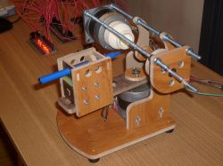
    I am proud of my Eggbot built last year:
    Egg - printer (Easter egg printer)

    Oddly enough, strange things were happening on the Arduino clone, and the original one works Ok.
  • #25
    Gizmoń
    Level 28  
    @perch And my friend made a surprise for me, I look at the topic and suddenly a very familiar construction :D For several years I had been going to build such a printer (or rather a plotter) for eggs, but the problem is that I always remembered about it when painting Easter eggs by hand :D Last year I remembered something about a week earlier, so I completed the entire project in a really fast pace. Its disadvantage is the large mass of the writing unit on the large arm. The engine waves it without a problem, but due to its jump movement, fading vibrations appear, sometimes a little visible in the pictures. In general, it works well enough that it will probably not be modernized, but if I wanted to build a second copy, I would definitely redesign this assembly, giving an electromagnet in the axis of rotation or not at all. There is a bit more of a fiddling with it, which I just didn't have time for at the time :D

    In my design, the pen works horizontally and is pressed against the egg by a very soft spring. Therefore, the clamping force does not depend on the angle of rotation of the arm, and the motor is also light, because it only overcomes the moment of inertia of the entire assembly. Only a tiny and light disc is tied rigidly to the pen, on which a spring rests on one side and an electromagnet lever on the other. The inertia of this set is therefore very small, so hitting the shell when leaving the pen does not damage the tip. The pen is pressed into the disc, so changing the color is very easy - just pull out one color and put in the other.

    Control from LinuxCNC + built-in fast half-step motor drivers (with ULN2803 as the power stage) + transistor to control the electromagnet. The control signal for the solenoid is simply the Z axis "DIR" signal.

    Egg - printer (Easter egg printer) Egg - printer (Easter egg printer)

    From the design presented in this topic, I will probably see the "egg clutch", these are the green o-rings (because they are o-rings, right?). I am also impressed with the functional spring printing. It is very rough, but it works and does not crack - I must admit that it is a surprise for me ;)

    PS
    I scaled the plotter control in such a way that 1 motor step = 1mm in the drawing. 400 steps per egg rotation, i.e. its circumference = 400mm in the picture. And there are no problems with hitting the circumference of the egg, because each one fits :D
  • #26
    tplewa
    Level 39  
    Gizmoń wrote:

    PS
    I scaled the plotter control in such a way that 1 motor step = 1mm in the drawing. 400 steps per egg rotation, i.e. its circumference = 400mm in the picture. And there are no problems with hitting the circumference of the egg, because each one fits :D


    Well, there is no problem with this, because you can always calculate how much we have per engine step. The more problem is that the eggs are not identical and each one would have to be measured and adjusted (it's about hand drawing to put it nicely on the egg - specifically on the "unfolded" plane whose length depends on the diameter of the egg) - and this is a bit of a pain. Although for some regular patterns you can write a script / applet, etc. that will generate them because it is enough to know the number of steps per full revolution - for example, something like that in matlab: https://www.youtube.com/watch?v= JfajQ4_hSN0 (I think I'll play with it myself ;) ot control over the serial port from matlab is trivial)
  • #27
    Gizmoń
    Level 28  
    But who needs a circuit? I will write again: it is enough to know how long the drawing corresponds to 1 egg revolution, and scale the graphics to this dimension. No matter if the egg is large or small, each one will make 1 revolution, so on each drawing it will cover the entire surface and come together nicely at the ends. You don't have to measure anything ;)

    A very cool idea is presented in this video. However, you do not necessarily need to control from Matlab - just write a programmer in any language that will generate the appropriate functions and save them as G-code. It is enough to use the G0 and G1 commands, so there is no great philosophy in this notation :D
  • #28
    tplewa
    Level 39  
    Gizmoń wrote:
    But who needs a circuit? I will write again: it is enough to know how long the drawing corresponds to 1 egg revolution, and scale the graphics to this dimension. No matter if the egg is large or small, each one will make 1 revolution, so on each drawing it will cover the entire surface and come together nicely at the ends. You don't have to measure anything ;)


    I am writing more about the situation to make the drawing look nice without distortions, etc. - as if to roll an egg onto a flat surface ... ;)

    However, as for the program, you can use whatever you want, but in matlab it is simply faster (and I have a licensed version in the company, so I have no problem) ;) and there is no need to play with the intermediate G-Code, which IMHO, firstly, is an excess of form over content in such a device, and secondly, the firmware that wants to use does not even support it ...
  • #29
    Gizmoń
    Level 28  
    The whole device is one great excess of form over content :D Oh, these are the transformations. It is not so much the diameter that would be needed as the entire profile of the longitudinal section. In my opinion, it is really difficult to implement, and without it the drawings don't come out so bad. And most importantly: after correction, maybe they would look perfect, but only when looking straight ahead. At a different angle, they would completely fall apart.
  • #30
    tplewa
    Level 39  
    Gizmoń wrote:
    The whole device is one great excess of form over content


    In general, as for the excess of form over content, I agree, and in simplified terms, it could be done knowing practically three dimensions, i.e. edges and center, and then the image should be properly transformed ;) All in all, the whole thing could even be crammed into this Inscape extension in python https://github.com/plex3r/plotink/tree/master/libraries

    Anyway, knowing life, how my daughter will get it, she will do it her own way, so I won't have much to say ;) just as much as mine, how will I play when starting ;)