How to compile and configure WLED for DMX on LilyGo T-CAN485 ESP32?
 .
.
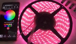
Here I show how to run an RGBW LED strip with DMX512 based on firmware WLED on a board with built-in RS485 support.
DMX512 is a communication protocol used primarily in stage lighting that allows multiple devices, including coloured LED strips, to be controlled over a single RS485 bus.
WLED is open source firmware for ESP8266 and ESP32 microcontrollers that enables control of addressable LED strips (WS2812, SK6812, APA102, etc.) and integration with popular automation systems and protocols such as MQTT, HTTP or Art-Net/DMX. With WLED, various lighting effects can be easily created and operated from the microcontroller.
For information on DMX512, I refer you to the previous topic:
LED strip with RS485 interface? DMX512 protocol - TM512C4 RGBW 24V .
For the presentation I will use the already described LilyGO with RS485:
LilyGO T-CAN485 - ESP32 for learning industrial connectivity, RS485 and CAN buses .
Plan of action .
Here are the next goals for today:
1. running a normal WLED compilation in PlatformIO
2. changing the WLED project settings to run the DMX controller already present in this environment
3. customising the existing DMX driver so that it runs on the LilyGO T-CAN485
4. uploading the custom WLED compilation to LilyGO and final configuration and testing with the strip
Basic WLED compilation .
We start the adventure by learning the basics of WLED compilation. It's basically all described on their official website:
https://kno.wled.ge/advanced/compiling-wled/
There are also recommendations for DMX on the same page, but unfortunately they are very incomplete.
https://kno.wled.ge/interfaces/dmx-output/
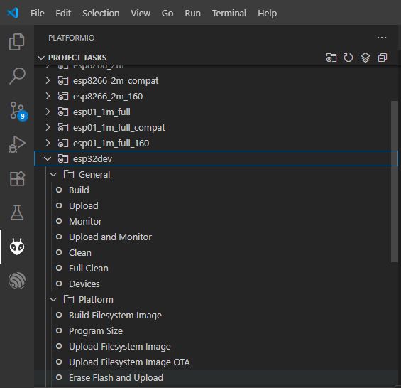
We download the repository from Github, execute npm install , and then open the project in PlatformIO (an extension from Visual Code). We already have the configurations ready there - I selected esp32dev . 'Build' operations etc. should already be working:
 .
.
Compilation and DMX support fixes .
It is time to modify the esp32dev settings. This configuration is defined in platformio.ini . There I have added DMX support to build_flags:
-D WLED_ENABLE_DMX
The -D switch simply adds #define WLED_ENABLE_DMX 1 to the build. Unfortunately, however, an error was issued on compilation:
usermods/audioreactive/audio_reactive.cpp:10:4: error: #error This audio reactive usermod is not compatible with DMX Out. #error This audio reactive usermod is not compatible with DMX Out. ^~~~~
I had to additionally remove the line with:
custom_usermods = audioreactive
from the same configuration section.
In the end it came out like this:
[env:esp32dev]
board = esp32dev
platform = ${esp32_idf_V4.platform}
build_unflags = ${common.build_unflags}
custom_usermods =
build_flags = ${common.build_flags} ${esp32_idf_V4.build_flags} -D WLED_RELEASE_NAME=\"ESP32_V4\" #-D WLED_DISABLE_BROWNOUT_DET
              -DARDUINO_USB_CDC_ON_BOOT=0
        -D WLED_ENABLE_DMX
lib_deps = ${esp32_idf_V4.lib_deps}
monitor_filters = esp32_exception_decoder
board_build.partitions = ${esp32.default_partitions}
board_build.flash_mode = dio
At this stage the compilation should work, but that's not all.... you still need to change the pin and run the RS485 on LilyGO ..
WLED has two separate DMX drivers. The first is in ESPDMX.cpp and is used on the ESP8266 and ESP32 C3 and S2:
Code: C / C++
The second is found in SparkFunDMX.cpp and is the one we are interested in today:
Code: C / C++
There you will find a hard-written (!) index of the pin from which data is sent via the UART (and then the corresponding circuitry converts this into RS485):
Code: C / C++
I have modified this block to use the pin definitions from the LilyGO developers:
Code: C / C++
Changing the pin is not enough - the transceiver still needs to be enabled on the LilyGO T-CAN485. In the end, I reworked the initWrite method in this way:
Code: C / C++
Configuration of WLED after uploading to ESP .
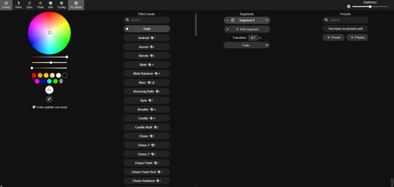
After uploading I had to pair the ESP with my WiFi. WLED creates its AP - the password is wled1234. The configuration page has an IP of 4.3.2.1. There you can enter our SSID and password for the device to join our network.
 .
.
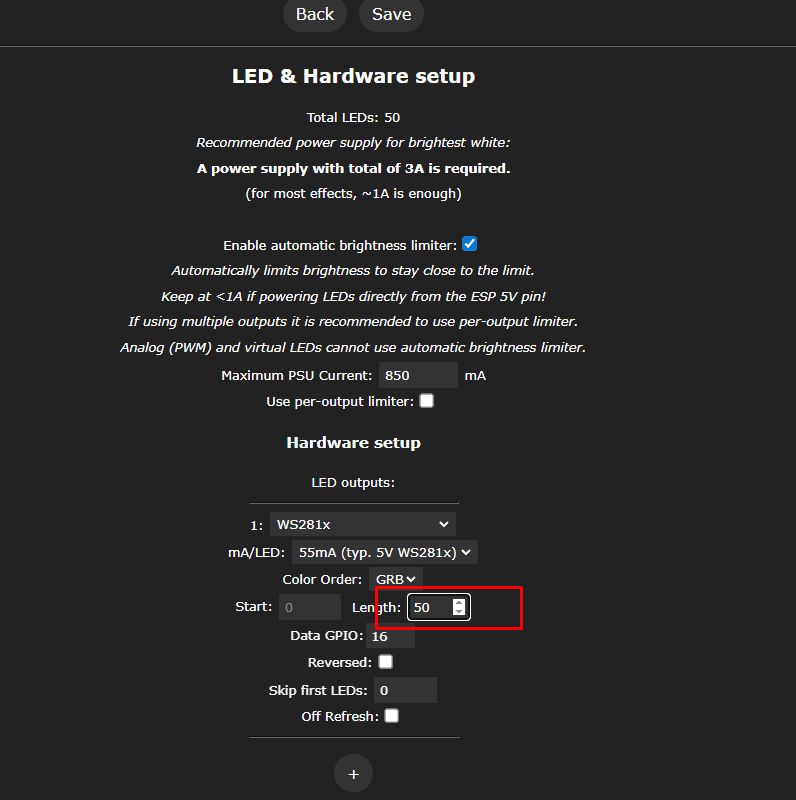
Then in Config->LED Preferences you need to set the number of pixels. I know, it's quite strange because here are the settings for WS2812 and similar, but that's how it works at the moment.
 .
.
What's more, the bar doesn't work stably for me when I set 50 LEDs here - I've set 40 for now.
Next we configure the DMX in Config->DMX Output. Next:
- channels per fixtures - channels per pixel, here 4, RGBW
- spacing between start channels - spacing between pixels, also 4
- start channel - initial channel - 1
- additionally we set the roles of the channels - successively RGBW
As in the screenshot:
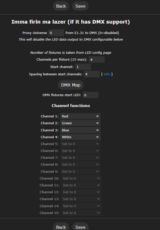 .
.
By the way, funny headline - "Imma firin ma lazer". Someone has a sense of humour.
We save and you can check the mapping by pressing the DMX Map button:
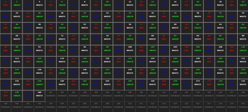 .
.
From now on the WLED should be able to control the strip with DMX .
Connecting the strip to LilyGO .
Let me remind you of the connection - basically as in the previous topic . Required:
- a separate power supply, here 24 V DC, according to the strip documentation
- RS485 from LilyGO (no common ground needed)
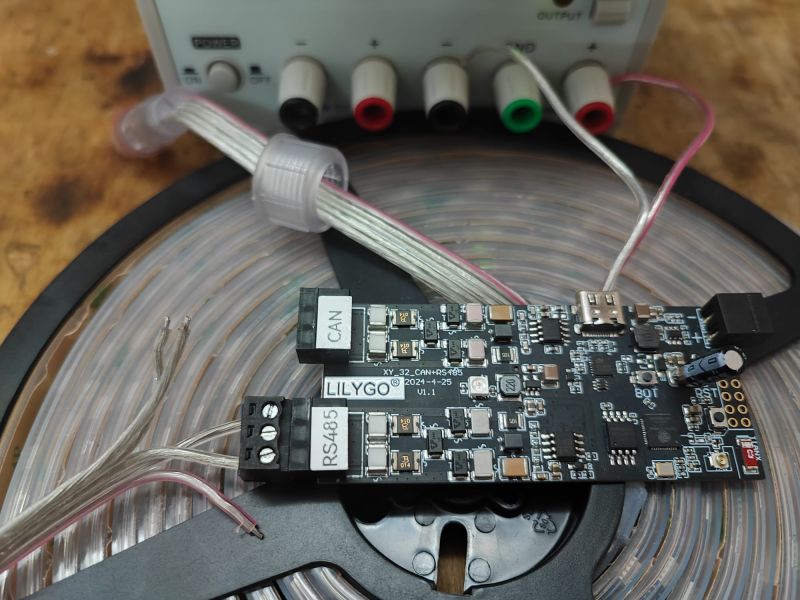 .
.
Results .
I have shown the results in the videos. The WLED can both animate the bar with a single colour (kind of like a single pixel), and of course it is also able to control individual pixels (here: sections) of the bar:
Measurements .
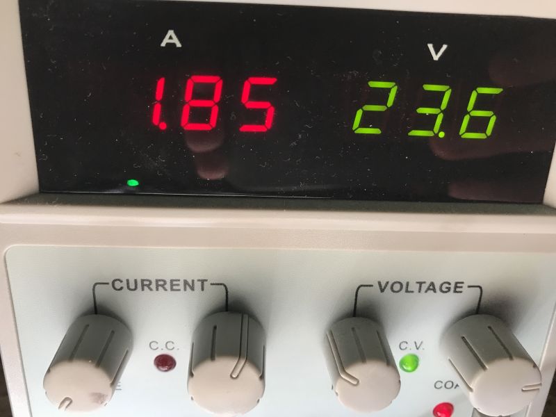
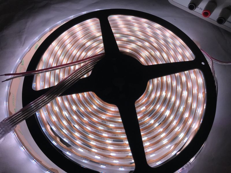
Finally, I still checked the power consumption of the whole strip as a test. I forced all channels to 255 (full brightness) in the DMX settings:
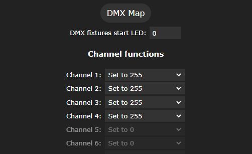 .
.
The result:
 .
.
 .
.
It appears that the full brightness of this strip is 43.66 watts.
Further steps needed .
It is worth recalling here the problem detected in the previous topic in the series . This strip draws 12 watts with all the LEDs off. This has not yet been solved by me - you will probably need a transistor and the ability to cut the 24V line when all the pixels are off. I don't know at this point if the WLED already has such a ready-made mechanism, or if I will have to implement it from 0. I will see in the next part.
Summary .
This is how I managed to get the DMX protocol working with the open source WLED software. The first surprise was how underdeveloped the support for this protocol is in this project. There is not even a mechanism there to select the UART pin. What's more, WLED uses two different libraries to send DMX (separately for ESP8266 and separately for ESP32), which also surprised me a bit, wouldn't it be easier to implement this together?
There was also a bit of a problem with the compilation, as the different compilation options are not compatible with each other and for this reason I had to disable the audio effects, which fortunately I don't need for anything.
The rest went smoothly, the only thing left to do was to add those bar power off when the LEDs are off.
That's it for now - do you use WLEDs in your projects? I also invite you to share your effects. In my case they are not ready yet...


Comments