FAQ
TL;DR: For LSC Smart XXL LED Strip (LN882HKI) on OpenBeken, users report -72 dBm Wi‑Fi RSSI and "Flash ran smoothly." Flashing works, but LEDs need correct GPIO roles; map pins with on‑device tools before fixing a template. [Elektroda, info207, post #21191735]
Why it matters: This FAQ helps LSC Smart XXL owners ditch Tuya and get working RGB+CCT control with OpenBeken, faster.
Quick facts:
- Firmware: OpenLN882H_1.17.656 flashed successfully; Hue and MQTT worked during testing. [Elektroda, info207, post #21191735]
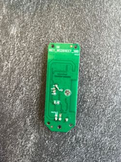
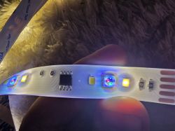
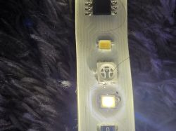
- LED type: Addressable strip with a single data line; marked “WS2811CCT.” [Elektroda, igfotfrank, post #21248567]
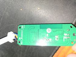
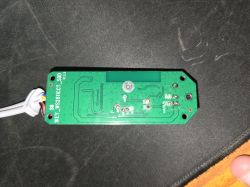
- Partial pinout seen: 6=RGB data (GPIOA6), 7=AlwaysHigh (LED V‑enable), 11=PWM3 (CW), 12=PWM4 (WW), 20=Btn0, 21=IRRecv. [Elektroda, igfotfrank, post #21248135]
- Power gating: Pin 7 must be set AlwaysHigh or LEDs stay dark. [Elektroda, igfotfrank, post #21248135]
- Status: No confirmed, public template posted in‑thread as of 2025‑04. [Elektroda, info207, post #21512118]
Quick Facts
- Firmware: OpenLN882H_1.17.656 flashed successfully; Hue and MQTT worked during testing. [Elektroda, info207, post #21191735]
- LED type: Addressable strip with a single data line; marked “WS2811CCT.” [Elektroda, igfotfrank, post #21248567]
- Partial pinout seen: 6=RGB data (GPIOA6), 7=AlwaysHigh (LED V‑enable), 11=PWM3 (CW), 12=PWM4 (WW), 20=Btn0, 21=IRRecv. [Elektroda, igfotfrank, post #21248135]
- Power gating: Pin 7 must be set AlwaysHigh or LEDs stay dark. [Elektroda, igfotfrank, post #21248135]
- Status: No confirmed, public template posted in‑thread as of 2025‑04. [Elektroda, info207, post #21512118]
What’s the working pinout/template for the LSC Smart XXL with LN882HKI?
A complete, verified template is not posted yet. Community testing shows: pin 6 = RGB data (GPIOA6), pin 7 = AlwaysHigh (LED voltage enable), pin 11 = PWM3 (CW), pin 12 = PWM4 (WW), pin 20 = Btn0, and pin 21 = IRRecv. Save roles, then test output. [Elektroda, igfotfrank, post #21248135]
How do I quickly find which pins control the LEDs?
Use the on‑device GPIO Doctor. “Open the ‘Web App’ and find the ‘GPIO Doctor’ tab.” Toggle each pin High/Low and observe the strip. 1. Open Web App. 2. Go to GPIO Doctor. 3. Toggle levels and note reactions. [Elektroda, p.kaczmarek2, post #21212857]
I flashed OpenLN882H but no LEDs light—what should I try first?
Enable the LED rail. Set pin 7 to AlwaysHigh to switch on LED voltage, then test PWM and the addressable data pin. Save, reboot if needed, and re‑test brightness and color. This gate must be on or outputs appear dead. [Elektroda, igfotfrank, post #21248135]
PWM won’t change light—should I try Relay roles in GPIO Doctor?
Yes—verify hardware response first. As advised, test whether LEDs react when you “use Relay roles in GPIODoctor” instead of PWM. If Relay toggles cause visible changes, the wiring and power gating work, and you can fine‑tune PWM later. [Elektroda, p.kaczmarek2, post #21197235]
Which pin carries the RGB data line for addressable LEDs?
Pin 6 (GPIOA6) routes to the strip’s single data line. Assign your addressable LED driver to this pin after confirming LED voltage is enabled. Then test color order and timing. [Elektroda, igfotfrank, post #21248135]
What LED protocol does this strip use—WS2812B or something else?
The strip is marked “WS2811CCT” and uses one data line. Treat it as an addressable LED chain and drive it via the pin 6 data input after enabling the LED supply. [Elektroda, igfotfrank, post #21248567]
How do I enable the CW and WW channels?
Map pin 11 to PWM3 (CW) and pin 12 to PWM4 (WW), then adjust duty via your OpenBeken UI or MQTT. Confirm LED voltage enable on pin 7 first, or CCT will remain off. [Elektroda, igfotfrank, post #21248135]
Why are my RGB LEDs stuck on white and dim, and not the full length?
This symptom was reported. It suggests incomplete configuration: missing LED voltage enable, wrong data pin, or incorrect addressable driver settings. Verify pin 7 is AlwaysHigh, data on pin 6, and then test addressable output. Re‑seat connectors and retest segments. [Elektroda, quegger77, post #21315199]
Does OpenLN882H boot and integrate (Hue/MQTT) on LN882HKI?
Yes. Users flashed OpenLN882H_1.17.656 successfully, enabled Hue, and confirmed MQTT worked for testing. Proceed to role mapping afterward to activate LEDs. [Elektroda, info207, post #21191735]
What does “0 drivers active, total 10” mean after flashing?
It indicates no active Roles yet. Open the UI, assign Roles to the relevant pins (e.g., AlwaysHigh, PWM, Button, IR), Save, and retest. Once roles are set, drivers activate. [Elektroda, info207, post #21191735]
How strong is the Wi‑Fi on this board?
One report showed RSSI at -72 dBm (Weak). Improve stability by testing near your access point during configuration. After mapping, you can relocate the controller. [Elektroda, info207, post #21191735]
Is there a confirmed working template available now?
Not yet in this thread. Multiple follow‑ups ask for a solution, with no posted, final template as of April 2025. Community testing continues. [Elektroda, info207, post #21512118]


