 .
.
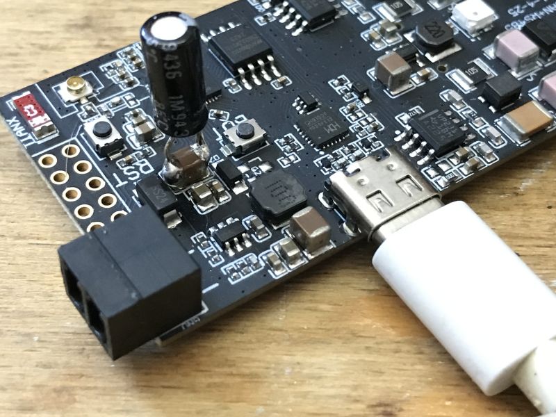
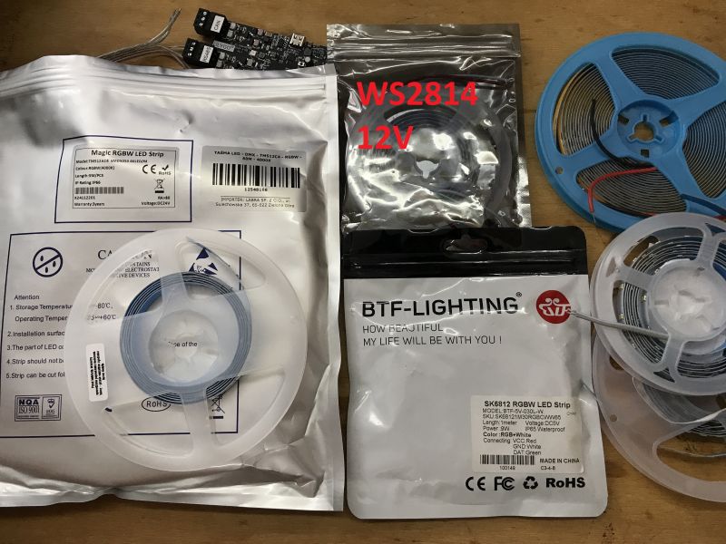
Here I will present an individually addressable RGBW LED strip (red, green, blue and white) based on the TM512C4 chip and operating on 24V. I will show here how its DMX512 communication protocol works and how it can be simply controlled from an RS485 ESP32. I will use the ESP32 LilyGO T-CAN485 board for the demonstration, as it makes things a bit easier and already has a built-in UART->RS485 transceiver.
 .
.
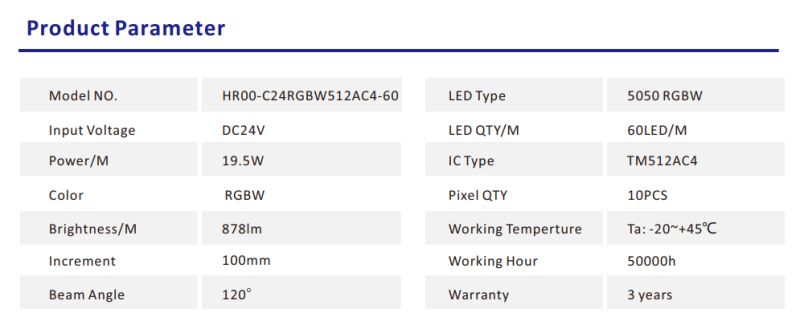
Let's start with the parameters of the tape. The tape has 60 SMD5050 LEDs per metre and is available in sections of 5 metres. There are four colours - in addition to the standard RGB, we also have 4000K white (neutral daylight) which allows for a variety of natural effects. The full model of the tape is HR00-C24RGBW512AC4-60.
 .
.
The controller used is an external chip and there is one for every six LEDs here, so we cannot control them completely individually.
 .
.
The manufacturer suggests dedicated K-8000C controllers for this, but we will figure something out ourselves:
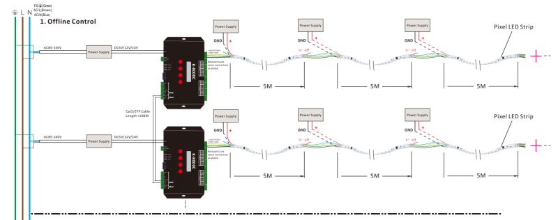 .
.
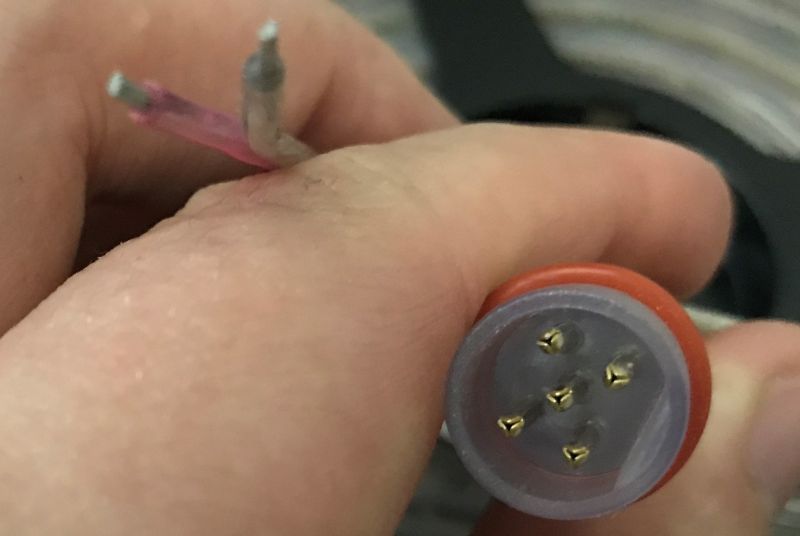
Let's see how the tape looks in practice.
 .
.
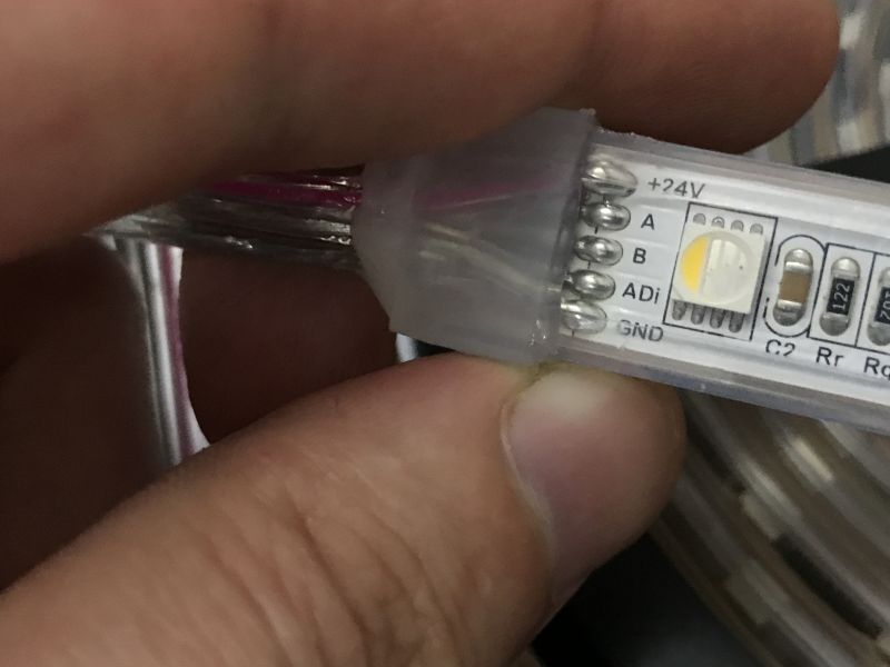
Here we have 5 lines, consecutively:
- +24V - power supply
- ADi - used for addressing
- A - RS485 lines
- B - RS485 lines
- GND - ground
The power supply is additionally led out. The tapes end with plugs for easy installation.
 .
.
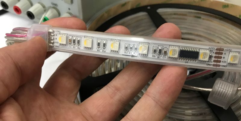
The tape is divided into fragments - one IC for six diodes:
 .
.
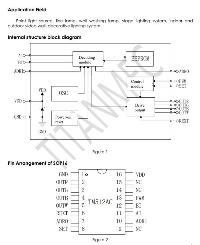
This chip is the TM512:
 .
.
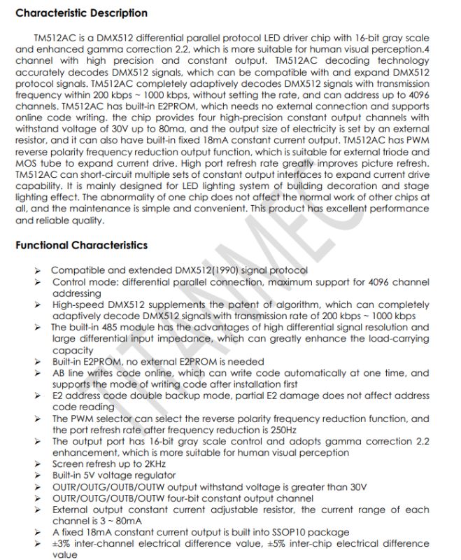
The TM512 is a DMX512 precision LED driver with 16-bit greyscale, gamma correction and adaptive decoding of up to 4096 channels, supporting DC and PWM modes for controlling external transistors. It is designed for LED lighting and animated stage effects
 .
.
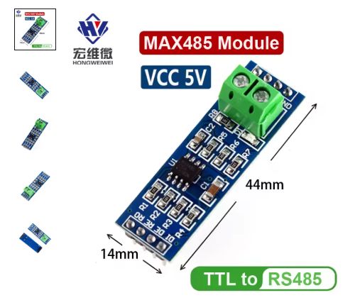
DMX512 is a popular protocol used in stage lighting that defines a fixed baud rate and a data packet of 512 channels. DMX512 may seem quite mysterious, but it basically boils down to sending individual values via RS485, i.e. via a UART + RS485 transceiver providing the appropriate levels. RS485 is a serial transmission standard that allows data to be sent over longer distances and under more difficult conditions than a regular UART. It allows operation in differential mode, meaning that the signal is transmitted as a voltage difference between two lines (A and B), which significantly increases noise immunity. Simply connect a suitable converter to the UART and you have RS485 - for example, the MAX485:
 .
.
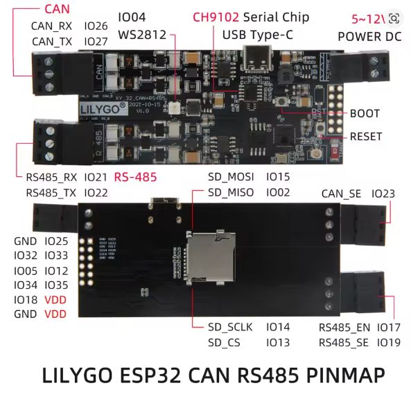
You can also use a ready-made one - for example the ESP32 LilyGo T-CAN485 module:
 .
.
RS485 from the code level is handled just like the UART - you simply need to initialise the port, set the baud and you are ready to send bytes.
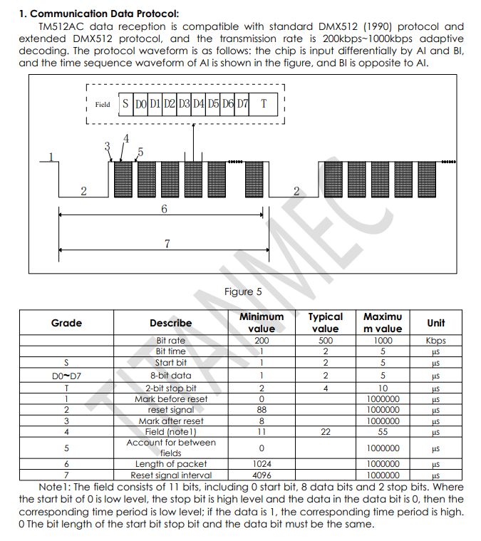
Now the question - how to send these bytes ? This is described in the 'Communication Protocol' section of the TM512 data note:
 .
.
The transfer rate (baud) is 250,000 bits per second. 513 bytes are sent (almost as in the name - DMX512), with the first byte not used. Usually one byte is per channel, so in the case of an RGBW strip we have 4 bytes per receiver. In this way, up to 128 such pixels can be handled.
In addition, DMX requires a proper packet start procedure, only then is the data sent. The default state of the line (idle) is high, then we set the low state to at least 88µs, then the high state to 8 µs and start the transfer. We will realise the start condition "manually" by operating on the pins, and the data sending will be performed for us by the Serial object.
I have run the example in PlatformIO under ESP32 with the Arduino SDK. Let's start with the most important one - sending DMX data:
Code: C / C++
Flush is used to send pending data from the serial port, then artificially generating a start condition and then I restart the port and send data with it.
This particular bar expects data in RGBW format - a byte per value. So auxiliary functions can be added, say:
- for setting all colours to a single value
- to clear the buffer
- to set a given pixel to the selected colour
Code: C / C++
Time to test. Finally, I'll discuss the connection - 24V for power and RS485 for lines A and B. There is no need for a common ground as RS485 is a differential signal.
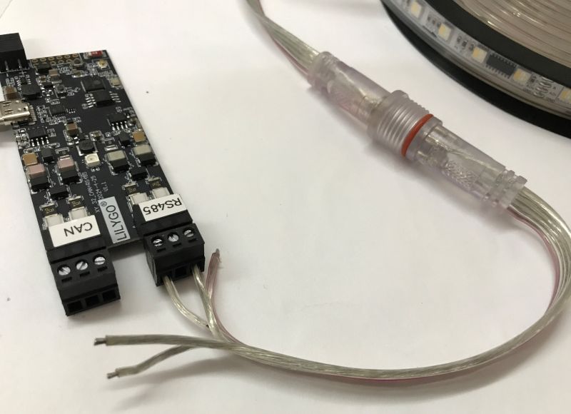
Red:
Code: C / C++
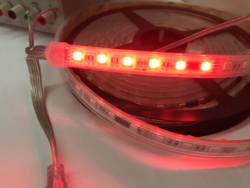 .
.
Green:
Code: C / C++
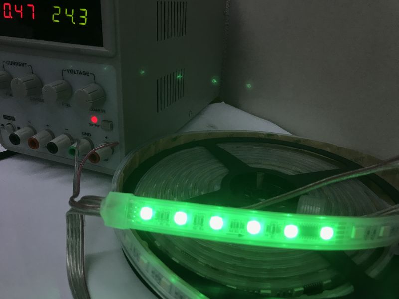 .
.
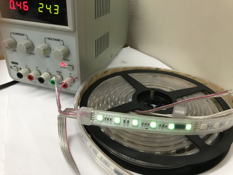
And so on. Green - dark:
Code: C / C++
 .
.
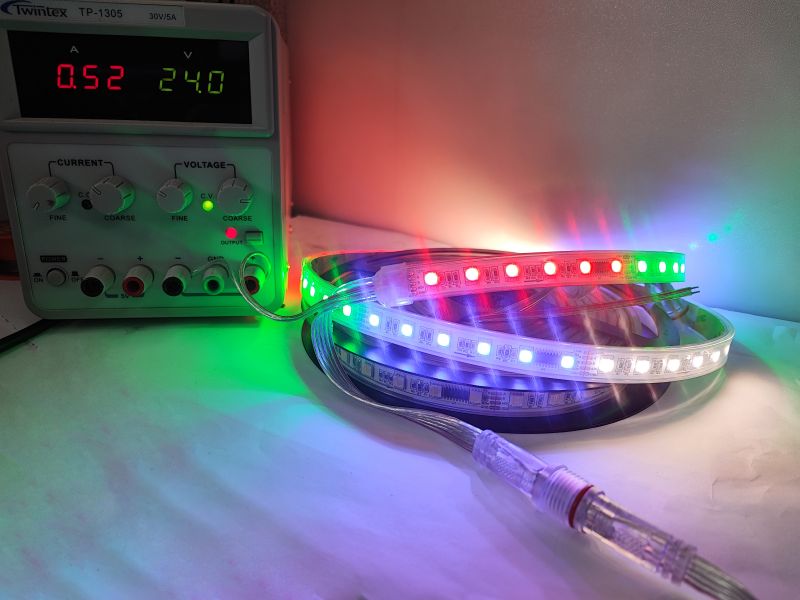
Various colours:
 .
.
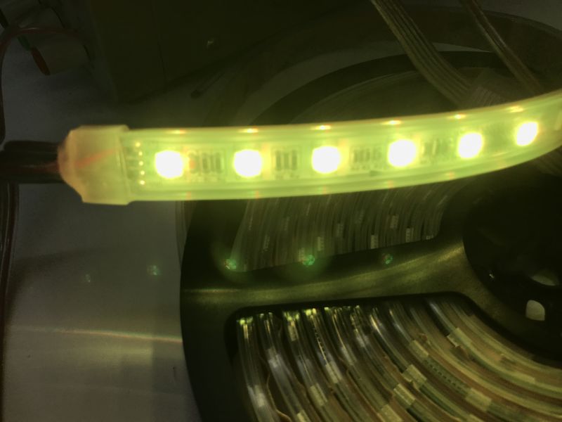
Now let's check the colour combinations. Yellow (red + green):
Code: C / C++
 .
.
Brightness level test:
Code: C / C++
Simple animation:
Code: C / C++
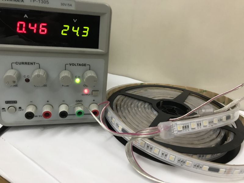
Let's examine the current consumption for a five-metre section of this strip.
All pixels off - 0.46A at 24.3V:
 .
.
All lit - 1.94A at 24.3V:
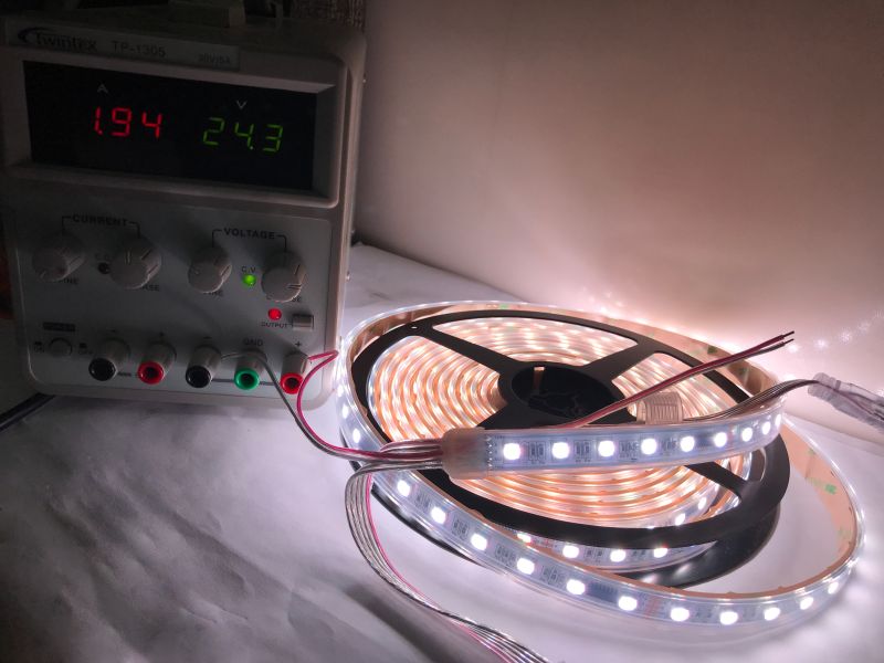 .
.
The conclusion imposes itself. 12W standby (!!!) and 48W during operation. That is, 36W light and 12W burned out.... on just what? It appears to be on the TM512AC power supply. You also need a resistor divider for this, on which a bit of power is lost:
 .
.
I haven't analysed this in any depth though. It definitely looks like the target circuit needs to detect the belt off and disconnect the VDD....
In summary , the DMX512 protocol is based on RS485 and consists of a simple start signal and data sent as individual bytes. The number of bytes per receiver can vary, in the case of the LED strip from the theme we had 4 bytes per controller (6 LEDs). The whole thing can easily be sent from your own program on the ESP32 platform, although you will also need an RS485 transceiver, such as the MAX485. This can be integrated into our board - for example if we use the Lilygo T-Can485.
The only problem I have encountered is the power consumption of the strip when the LEDs are off - it looks like you will need a transistor to turn the whole thing off when no LED is on. I was a bit taken aback by this at first, I don't have a second unit at the moment to check if this is the case in every instance.
This was a basic demonstration and I managed to achieve the desired effect here, although this is not the end of my adventures with this strip. I plan to at least still:
- run it in my firmware open source , along with an extra pin and power disconnect transistor (pity about those 12W...).
- run it with WLED (I'm afraid you'll need to compile the batch yourself)
- investigate and describe the role of the as yet unmentioned addressing pin
That's it for now, the strip itself looks promising, I wonder how it will come out after assembly. I really like the presence of white in it, and the 6 LEDs per controller can be overcome, it is not strictly "per pixel" but it is possible to animate.
Have you used LED strips or other DMX512 controlled devices? .
[i]I have included the full code used for the presentation in the appendix (PlatformIO project) .
Cool? Ranking DIY Helpful post? Buy me a coffee.


