logo elektroda
logo elektroda
X
logo elektroda
ADVERTISEMENT
Treść została przetłumaczona polish » english Zobacz oryginalną wersję tematu
  • #31 18275040
    noel200
    Level 27  
    I have one input configured as probe in the machine program and in the controller. I have one wire glued to the pcb and the other with a crocodile clip is attached to the drill after the change, I hammer the command and the machine goes down until the drill touches the pcb. Then I do zero Z.
  • ADVERTISEMENT
  • #32 18275075
    neo62
    Level 17  
    I managed to find it, I thought I did not have a break in the panel and I have to type from my finger but it is. I still have to fight some g-code. But basically everything works, thanks for the answer.
  • ADVERTISEMENT
  • ADVERTISEMENT
  • #34 18696201
    tbunio
    Level 20  
    Does anyone know how to mill unnecessary copper?
  • ADVERTISEMENT
  • #35 19193220
    lukasixthm
    Level 23  
    tbunio wrote:
    Does anyone know how to mill unnecessary copper?


    The pcbgcode-setup, generation options, Board window script, where "Isolation" is in the "Maximum" line, enter for example 25mm. Then there will be no copper within 25mm from the track, the tracks will of course stay.


    [/movie]
  • #36 19273578
    encelados
    Level 10  
    As for me - a revelation.
    Even for highly hobby applications, such as: 3 PCBs per year. And I don't need 2-3 mils insulation. 12 mils is as much as 0.3 mm.
    How would I play with various chemical methods would be:
    1. Photochemically - laser printer needed, photosensitive laminate, UV exposure device, exposed laminate development, developer temperature, etching of photosensitive laminate induced, etchant temperature, cuvettes, tongs, gloves, glasses, inhalation of vapors, developer storage, etchant storage.
    2. Thermal transfer - laser printer needed, iron (although it can also be transferred without iron, cold), etching of the laminate covered with toner, temperature of the etcher, cuvette, tongs, gloves, glasses, inhalation of vapors, storage of the etchant.

    And here we have the physical removal of the copper layer from the ordinary (not any photosensitive) laminate to a depth of about 0.04 mm using CNC milling. You do not need any: laser printers, UV irradiators, cuvettes, tweezers, gloves, glasses. There is no inhalation of any chemical fumes. There is no need to store any hazardous chemical solutions.
    It would be enough to:
    1. Eagle from pcb-gcode.ulp.
    2. Mini CNC milling machine (included in the price of a new monochrome laser printer), such as this: https://allegro.pl/oferta/cnc3018-pro-grawerka-laserowa-sterowanie-9152266028.
    3. Engraving cutter 0.2 mm, for example: https://allegro.pl/oferta/frez-vhm-grawerski-...QoIPTN50WwNXfsE-O3RVqhCna5g5RVqhCna5g5RVqhCna.
    3. 0.9 mm drill bit, for example: https://allegro.pl/oferta/wiertlo-weglik-widia-do-plytek-pcb-0-9-mm-9505195133.
    4. 0.5 mm multi-edge cutter, for example: https://allegro.pl/oferta/frez-diamentowy-wieloostrzowy-pcb-0-5-x-3-175-x-38-9538600240.

    I only design PCBs in Eagle. I fire up pcb-gcode.ulp. I put a piece of laminate on the milling machine, fire the appropriate TAP or CNC files one by one, after milling the paths, I change the 0.2 mm engraving cutter to a 0.9 mm drill, drill holes, change the drill bit to a 0.5 mm cutter, cut (mill) the plate after contour. And already. Clean job. Maybe the only nuisance is milling dust and some noise.

    And I have a transfer, laser printers, toners, whether original or substitutes, chalk paper, or for thermal transfer, or slippery from colored newspapers, acetone mixed with isopropanol or in such proportion or other, iron, litter boxes, tongs, glasses, aerators, etchants, UV plateseters, developers, chemical rubbing and inhaling chemicals. A lot of nuisance, and you never know how a plate made with transfer methods will come out.
    :)
  • #37 19273968
    yogi009
    Level 43  
    And this will cut the Atmega8 pads in the TQFP housing?
  • #38 19274495
    lukasixthm
    Level 23  
    yogi009 wrote:
    And this will cut the Atmega8 pads in the TQFP housing?


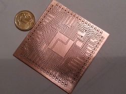
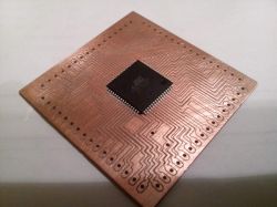
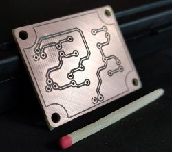
    Of course. No problem. I go down to 0.08mm.
    Milling PCBs designed at Eagle

    Milling PCBs designed at Eagle
  • #39 19276309
    yogi009
    Level 43  
    Precision cuts, but poorly designed paths, as it stands, make it difficult to solder aesthetically.
  • #40 19311594
    PiotrPitucha
    Level 34  
    Hello
    You've gone overboard with this aesthetic soldering :)
    You put the solder mask on and the soldering looks like it is from the store.
    There are a lot of examples on the web for making soldermask, the simplest
    paint over the entire tile and then remove the mask from the pads with a laser
    or a milling cutter.
    best regards
  • #41 19363777
    encelados
    Level 10  
    In the end, I also tried:

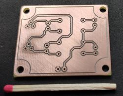
    Milling PCBs designed at Eagle
    Milling PCBs designed at Eagle


    6 minutes of everything (including drilling holes and milling the board outline).
    :D

    Just milling / engraving to a depth of Z-0.04 mm. No more is needed.
    For THT assembly, drilling holes in the cnc with a cnc drill bit with a diameter of 0.6 mm is enough. No more is needed.
    Too "tight" holes drilled in the CNC with a 0.6 mm drill - you can always enlarge "by hand" using a larger drill.
  • #42 19675687
    neo62
    Level 17  
    lukasixthm wrote:
    tbunio wrote:
    Does anyone know how to mill unnecessary copper?


    The pcbgcode-setup, generation options, Board window script, where "Isolation" is in the "Maximum" line, enter for example 25mm. Then there will be no copper within 25mm from the track, the tracks will of course stay.


    [/movie]


    I fight it and fight it, but when I set it, let's say 25mm, it even eats my paths. For example, setting 2mm is ok as long as there is no other track next to it.

    Forgive me for digging up, but nowhere else have I found anything on this topic.

Topic summary

The discussion revolves around milling PCBs designed in Eagle using the pcb-gcode.ulp plugin, which simplifies the process of generating G-code for CNC milling. Users share their experiences, including setup instructions, troubleshooting issues with layer generation, and the effectiveness of milling compared to traditional etching methods. Key points include the importance of machine speed, the need for proper ULP settings to generate drilling files, and the challenges faced with hole alignment and depth during milling. Various users also discuss alternative software like FlatCAM for Gerber file support and share tips for achieving better results in PCB design and milling.
Summary generated by the language model.
ADVERTISEMENT