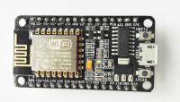
I have an ESP8266 12E on Devboard (without nodemcu):
 .
.
I have 2 MCP3208 analog-to-digital converters connected to this ESP via SPI and an MCP1501-18E/SN reference voltage source.
I get errors like this on the UART all the time. The typical "Blink "is working.
.
The whole thing should look more or less like what I have on the Arduino:
 .
.
I've been looking on the internet for a solution to such a problem. People wrote to update the soft because it helped someone. I uploaded the latest firmware version - ESP8266NONOSSDK-2.1.0
 .
.
Elsewhere they have written that the USB has too little current capacity and the ESP should be connected to an external power supply. On the one hand this seems sensible as the ESP draws a lot of current, nevertheless I have usb 3.0 from my keyboard which has a current capacity of 750mA and I am NOT using wifi alone for the time being. The bare calculations I could do on the Arduino. Still, it wouldn't hurt to try.
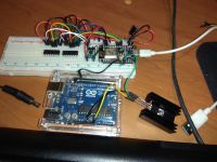
I used the Arduino as a power supply. I connected a 12V / 1.5A power supply to it. Then this 12V via VIN to the LM1117T 3.3V stabiliser, and from it to the 3.3V and GND pins on the esp, and then I assembled such a circuit as in the picture below. Same thing.
 .
.
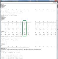
As I connected the measured quantity under one channel on the ADC, it was sometimes seen correctly:
 .
.
Further random values followed again.
Does anyone have any idea why this doesn't want to work? Once I managed to make it work on a small contact board, but with no voltage source and only 1 converter. Now it doesn't even want to work in this configuration. I have been checking that everything "contacts". I even borrowed a second large contact board from a friend. Still the same thing.
Thank you very much in advance and best regards
edit: I found something like this:
I thought that since it's an all-in-one board there was no need to connect the "CH_PD+RST" pin. Unfortunately nothing helps at my place.
edit2: I think I found the culprit.
https://techtutorialsx.com/2017/01/21/esp8266-watchdog-functions/
The ESP has a "watchdog" that when it doesn't receive a signal, it resets the chip. It's software and hardware. Aha, cool. The problem with me is that it resets once immediately, sometimes after a long time. I try to disable it with these commands however unsuccessfully
Interestingly, the ESP.wdtEnable(1000); function takes a time argument and doesn't use that - Chinese technical thought knocks it down.
edit3:
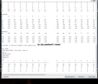
Sometimes it won't fire, I have to reset and plug it in again. But once it has counted on the UART it takes longer. Partial success, because it crashes and resets again. The program is 100% fine without memory leaks, as it worked perfectly on the Arduino. I only changed the pin names to fit under ESP. Then I wanted to add WiFi, but I can't manage it.
.
Added after 14 [hours] 50 [minutes]: .
I have discovered the cause but cannot logically explain it.
I will present it in 2 videos:
1. https://www.youtube.com/watch?v=GStJmICuyp8
2. https://www.youtube.com/watch?v=L1QBTgNJogQ
On the first one the WiFi is connected to the prototype board. Please disregard the component on the left, I forgot to unplug it, but it is unconnected and does not affect the "not working".
On the other WiFi hangs up and works without any problems. It immediately switches on.
As I wrote above, on the small contact board it worked for me once. Now neither on the 2 large boards nor on any small board works.
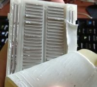
There are no short circuits (photo below). Is anyone able to explain this logically?
 .
.
edit2: corrected video.
Problem partially solved. I simply don't put the module all the way onto the contact plate, only half way up. Everything contacts and works. Apparently some stress (?) is created. Even re-soldering pins 2.54 didn't help. Strange.
 .
.
I have 2 MCP3208 analog-to-digital converters connected to this ESP via SPI and an MCP1501-18E/SN reference voltage source.
I get errors like this on the UART all the time. The typical "Blink "is working.
Code: C / C++
 .
.
I've been looking on the internet for a solution to such a problem. People wrote to update the soft because it helped someone. I uploaded the latest firmware version - ESP8266NONOSSDK-2.1.0
 .
.
Elsewhere they have written that the USB has too little current capacity and the ESP should be connected to an external power supply. On the one hand this seems sensible as the ESP draws a lot of current, nevertheless I have usb 3.0 from my keyboard which has a current capacity of 750mA and I am NOT using wifi alone for the time being. The bare calculations I could do on the Arduino. Still, it wouldn't hurt to try.
I used the Arduino as a power supply. I connected a 12V / 1.5A power supply to it. Then this 12V via VIN to the LM1117T 3.3V stabiliser, and from it to the 3.3V and GND pins on the esp, and then I assembled such a circuit as in the picture below. Same thing.
 .
.
As I connected the measured quantity under one channel on the ADC, it was sometimes seen correctly:
 .
.
Further random values followed again.
Does anyone have any idea why this doesn't want to work? Once I managed to make it work on a small contact board, but with no voltage source and only 1 converter. Now it doesn't even want to work in this configuration. I have been checking that everything "contacts". I even borrowed a second large contact board from a friend. Still the same thing.
Thank you very much in advance and best regards
edit: I found something like this:
Quote:.ets Jan 8 2013,rst cause:2, boot mode:( 3,7) <-- reboot by reset pin - Mode Flash (boot the sketch)
I thought that since it's an all-in-one board there was no need to connect the "CH_PD+RST" pin. Unfortunately nothing helps at my place.
edit2: I think I found the culprit.
https://techtutorialsx.com/2017/01/21/esp8266-watchdog-functions/
The ESP has a "watchdog" that when it doesn't receive a signal, it resets the chip. It's software and hardware. Aha, cool. The problem with me is that it resets once immediately, sometimes after a long time. I try to disable it with these commands however unsuccessfully
Interestingly, the ESP.wdtEnable(1000); function takes a time argument and doesn't use that - Chinese technical thought knocks it down.
edit3:
Sometimes it won't fire, I have to reset and plug it in again. But once it has counted on the UART it takes longer. Partial success, because it crashes and resets again. The program is 100% fine without memory leaks, as it worked perfectly on the Arduino. I only changed the pin names to fit under ESP. Then I wanted to add WiFi, but I can't manage it.

Added after 14 [hours] 50 [minutes]: .
I have discovered the cause but cannot logically explain it.
I will present it in 2 videos:
1. https://www.youtube.com/watch?v=GStJmICuyp8
2. https://www.youtube.com/watch?v=L1QBTgNJogQ
On the first one the WiFi is connected to the prototype board. Please disregard the component on the left, I forgot to unplug it, but it is unconnected and does not affect the "not working".
On the other WiFi hangs up and works without any problems. It immediately switches on.
As I wrote above, on the small contact board it worked for me once. Now neither on the 2 large boards nor on any small board works.
There are no short circuits (photo below). Is anyone able to explain this logically?
 .
.
edit2: corrected video.
Problem partially solved. I simply don't put the module all the way onto the contact plate, only half way up. Everything contacts and works. Apparently some stress (?) is created. Even re-soldering pins 2.54 didn't help. Strange.


