logo elektroda
logo elektroda
X
logo elektroda

ALSTER controller does not switch on after 12V voltage is applied

reed 1863 4
ADVERTISEMENT
Treść została przetłumaczona polish » english Zobacz oryginalną wersję tematu
  • #1 16938253
    reed
    Level 17  
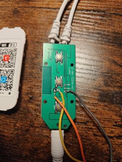
    I have a problem with the controller as in the subject line. It has stopped working. I don't know under what circumstances and I need to bring it back to life. It was used as a door opener "release". Used red (+), black (ground) and green (control, I think) wires. When 12V is connected, not even the control LED (on the side of the controller) lights up.

    The controller is, at first glance, very simple and in total not much should go wrong with it but .... Is there anything I can do to fix it at home? Electrolytes are fine, nothing looks "stoned". Does anyone have a schematic diagram for this controller? Or should I give up and buy another one?

    Can you tell from the pictures?

    ALSTER controller does not switch on after 12V voltage is applied
    ALSTER controller does not switch on after 12V voltage is applied
    ALSTER controller does not switch on after 12V voltage is applied .
    .
  • ADVERTISEMENT
  • #2 16940936
    marek216
    Level 43  
    reed wrote:
    Can I somehow by home means try to fix it?
    .
    Meter + soldering iron.
    reed wrote:
    nothing looks "stoned"
    .
    I was taught that electronics are measured, not looked at.
    reed wrote:
    Maybe you can tell something from the pictures ?
    .
    The fairies will be back next week after the New Year's Eve party.
  • ADVERTISEMENT
  • #3 16944467
    reed
    Level 17  
    marek216 wrote:
    reed wrote:
    Can I somehow try to fix it by home means?

    Meter + soldering iron.

    Yes, I have.

    marek216 wrote:
    reed wrote:
    nothing looks "stoned"
    .
    I was taught that electronics are measured, not looked at.

    Congratulations that someone had the opportunity to teach you this. I, unfortunately, am learning on my own. That's why I'm asking for help - if only for a diagram of this controller....

    marek216 wrote:
    reed wrote:
    Maybe you can tell from the pictures ?
    .
    The fairies will be back next week after the New Year's Eve party.

    I have uploaded illustrative photos. Maybe someone has an association with the controller. Maybe there is a problem that is typical. Or maybe I have missed something.

    Anyway - thank you for your help.
  • ADVERTISEMENT
  • #4 16944992
    xury
    Automation specialist
    reed wrote:
    When 12V is connected, not even the control LED (on the side of the controller) lights up.
    .
    This already suggests that there is something wrong with the power supply, and this in turn suggests that there are e.g. linear stabilisers, operational amplifiers, voltage converters, current sources etc. on the pcb that may not be working. It would be advisable to take a closer look at them. By "take a closer look" I mean to take measurements.
  • #5 16945760
    reed
    Level 17  
    xury wrote:
    There is already a conclusion that there is something wrong with the power supply
    .

    There is a 5Vdc PIC16F636 supply to the microcontroller.


    Does anyone have a schematic diagram of this controller ?
ADVERTISEMENT