logo elektroda
logo elektroda
X
logo elektroda

NIVONA Caferomatica 830 Coffee Machine: Damaged Display Repair, AliExpress Replacement

paps79 278955 462
ADVERTISEMENT
Treść została przetłumaczona polish » english Zobacz oryginalną wersję tematu
  • #211 18325448
    VovaSova1980
    Level 2  
    So I put together a display. Thanks Amigos.
    NIVONA Caferomatica 830 Coffee Machine: Damaged Display Repair, AliExpress Replacement NIVONA Caferomatica 830 Coffee Machine: Damaged Display Repair, AliExpress Replacement NIVONA Caferomatica 830 Coffee Machine: Damaged Display Repair, AliExpress Replacement
  • ADVERTISEMENT
  • #212 18327627
    VovaSova1980
    Level 2  
    Всё получилось. Спасибо, Amigos.
    NIVONA Caferomatica 830 Coffee Machine: Damaged Display Repair, AliExpress Replacement NIVONA Caferomatica 830 Coffee Machine: Damaged Display Repair, AliExpress Replacement NIVONA Caferomatica 830 Coffee Machine: Damaged Display Repair, AliExpress Replacement
  • #213 18328895
    amigos
    Level 16  
    And great. Thank you for the info. I'm glad it worked out. Congratulations, because you need some work and willingness to solder.

    Greetings!
  • ADVERTISEMENT
  • #214 18331378
    Smoczy
    Level 19  
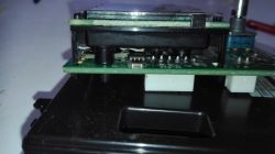
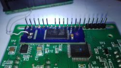
    NIVONA Caferomatica 830 Coffee Machine: Damaged Display Repair, AliExpress Replacement NIVONA Caferomatica 830 Coffee Machine: Damaged Display Repair, AliExpress Replacement NIVONA Caferomatica 830 Coffee Machine: Damaged Display Repair, AliExpress Replacement NIVONA Caferomatica 830 Coffee Machine: Damaged Display Repair, AliExpress Replacement NIVONA Caferomatica 830 Coffee Machine: Damaged Display Repair, AliExpress Replacement NIVONA Caferomatica 830 Coffee Machine: Damaged Display Repair, AliExpress Replacement
    This is my solution. There is no problem with jumping lines. In the event that this problem occurs, there is the signal delay / WR option.
    If anyone is interested, I have some redundant tiles.
    Regards, Łukasz
    PS Sorry for the not very aesthetic background of photos :)
  • #215 18331425
    amigos
    Level 16  
    Most importantly, something has been created and works. Aesthetics does not matter. Congratulations. Will you give something more? Some shemacik, or at least what layout did you use? It's hard to read from the photo.
    There was no problem with the lines on this display. I am waiting for someone to finally do a project where there will be no problem with the lines in ssd1306, ssd1309, or spd0301 ;)
  • #216 18331484
    Smoczy
    Level 19  
    39VF512 with a modified content so that you can "pass" the /WR signal through it.
    My solution only requires:
    1. After removing the housing, unsolder the display board from the pins
    2. Raise the plastic strip on the IDC pins to about half the height
    3. Solder the plate to the goldpins according to the picture, slide the plastic strip as low as possible
    4. undercut one of the display pins so that it misses the added board
    5. Replace the display on the original board
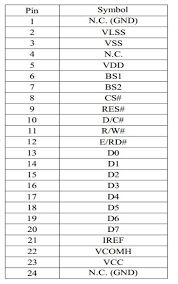
    6. Cut off the D0 pin (7th pin counting from the power supply side) so that it does not get to the display board. It has to be connected to the module.
    7. Solder the display board
    8. Connect the square pad from the module with a cable instead of the cut off D0 pin (there are two next to each other, oval and square).
    9. Check operation, if there is a problem with errors on the display, you should also connect the /WR signal through the module (round pad from the module).

    The whole work takes no more than 15 minutes, with average skill in soldering.
    The board on which I made the project is one-sided (for this reason, one jumper was necessary, visible in the picture)
    Further questions, please write.
    Regards, Luke
  • #217 18338219
    RLG
    Level 2  
    Greetings
    Amigos, in reference to #198 post, did the Pcb house supplied the parts and assembled it too?
    Thanks
    RLG
  • ADVERTISEMENT
  • #218 18341978
    Artii80
    Level 11  
    I have a coffee machine with the same condition.
    I bought the display on Ali and connected to the old board for trial. I intend to use the solution of honorable forum users.

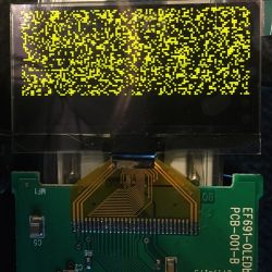
    I attach a photo of what appeared on the display. I bet on power disturbances. Has anyone had a similar case? What to exchange? Capacitors in the power supply?

    NIVONA Caferomatica 830 Coffee Machine: Damaged Display Repair, AliExpress Replacement
  • #219 18341993
    amigos
    Level 16  
    Carefully check how you soldered it. You don't have a short circuit between the pads or you didn't tear the path when desoldering the previous one? I am looking at the photo on the phone and in enlargement I have poor quality, but the second pad from the left looks strange to me.

    Added after 10 [hours] 49 [minutes]:

    RLG wrote:
    greetings
    Amigos, referring to post # 198, did the Pcb house supply the parts and assemble them as well?
    Thanks
    RLG


    Hello. I do not repair displays. Please do not write for repair on priv. I do not sell any parts or tiles because I do not sell them. I got involved in this project because I like challenges ;)
    Everything you need is in the subject and you need to somehow manage or find someone who will do it to you. Of course, I am happy to answer questions if I can help.

    Greetings!
  • #222 18353757
    milcin68
    Level 2  
    amigos, thanks.
    No gaps on this display?
  • #223 18353856
    amigos
    Level 16  
    This is the one in post # 195. There is no break.
  • #224 18358187
    P48
    Level 12  
    Hello everyone. Thank you to colleagues Amigos and Satanistik for the resulting project. The display works like new. Merry Christmas and best regards.
  • #225 18358217
    amigos
    Level 16  
    Thank you. Wishes for a healthy and peaceful Christmas for everyone interested in the subject.
    Thank you for the info about effects. I enjoy every signal that Nivona was saved and someone is using the project.
  • #226 18358331
    Rosenkopf
    Level 8  
    I can only join P48.

    Greetings and Merry Christmas :D
  • #227 18358600
    mipix
    Level 38  
    Hello

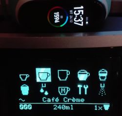
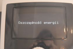
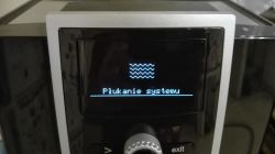
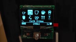
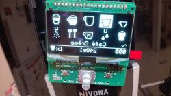
    Coffee machine display with icons of beverage types and volume in milliliters. Display with uneven backlighting of horizontal lines resting on documentation. Coffee machine display with bluish icons and text.

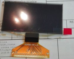
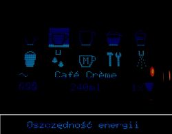
    This display works, there is no shortage of lines, but it has uneven lighting for horizontal lines. Slight but visible. In the third photo the contrast is turned up so that you can see the difference in brightness better. White was ordered, but this one is very light blue, almost white. Due to the fact that this is not an HD TV but a coffee machine, it is quite OK.

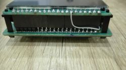
    Screen displaying the text Oszczędność energii with a bluish tint. Coffee machine display with System Rinse message. Small coffee machine display screen with beverage icons and Café Crème text. Control panel display of a coffee machine with icons and text. Side view of a display mounted on a printed circuit board. Close-up of a circuit board with a mounted display module and soldered pins. Electronic display with mounted goldpins and a bridge on the wire.

    I used the SMOCZY solution, but I added a goldpin socket and a bridge on the cable. I soldered myself, but it works. I have a removable display.

    Merry Christmas
  • ADVERTISEMENT
  • #228 18411279
    AnotherUsername
    Level 1  
    Sorry for responding in English.

    Your solution looks great and simple. I would like to do this to my own machine as well.
    I see you used Smoczy's design, but I can't see a PCB file. Could you (or Smoczy) share this? Also, which chips do I need to order and solder onto the PCB to make this work?

    Finally, could you confirm this is the correct way of attaching it?
    1) Solder chips on new PCB and wire on the big pad
    2) Remove old displayboard
    3) Cut pin 7 from the mainboard
    4) Solder the new PCB onto the mainboard
    5) Solder the old displayboard with new display on top of it
    6) Connect the wire from the new PCB to pin 7 from the displayboard

    Thank you!
  • #230 18421716
    Smoczy
    Level 19  
    Well, but the cash register is considerable, and my solution is the cheapest and fastest to use, so far, but you have to solder.
  • #231 18421757
    amigos
    Level 16  
    Unfortunately. It doesn't go cheap and yours is certainly cheaper. As for speed, for an ordinary user who has no idea about soldering, ebaya is perfect. Unscrews the module, cuts off the dowels at the plate with a cutter and applies a new plate. It doesn't even have to desolder the old one, and it is advisable to cut the length to fit the socket. The project is completely professionally made, although probably based on a similar SST flash as yours. But I envy the tile design ;) You can see that the guy knows "what to eat with." Somehow I didn't have time and inspiration to perfect my work :D For me it looks like a manufacturer's repair element.
  • #232 18423746
    dzako071
    Level 8  
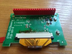
    Heh, in terms of connections I did yesterday the same as this ebay seller, i.e. from the side of the board with the display I installed the socket, and from the pcb side with the control I cut the goldpins. I also added a 32-pin tab socket so that one leg hangs, I fitted and cut the tape, so everything is slipped :) Still inverted image.

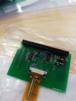
    Close-up of a PCB with an attached OLED display module. Green PCB with various electronic components, including a red connector.
  • #233 18423773
    amigos
    Level 16  
    I also used a pin connector, but only because of the need to access components during testing and frequent disassembly. So this is not new to ebay, but easier to install for a layman ;) I do not suspect that I would ever have to replace an already made display.
  • #234 18425457
    dzako071
    Level 8  
    After connecting the display, I had a problem, when the coffee machine is turned on, it goes into standby mode with these lines instead of the time (because it is not set).
    After attempting to enter the standby mode, literally for a split second the time to set appears, then the display goes out and the machine no longer reacts to pressing the selection button. Generally, after turning the power on / off it lights up once and once not. As the display tilts a little further from the pcb, it turns on more often and when it sticks to the pcb, it doesn't turn on at all.
    I do not know if I damaged any path during desoldering and chipped the coil housing, but I think this is not a problem. Anyone got any idea? Thanks in advance.
  • #235 18425476
    amigos
    Level 16  
    Are you writing about connecting to an original board without modification? As in the pictures above?
  • #236 18425502
    dzako071
    Level 8  
    Yes, I will make a plate for your project anyway, but I wanted to drink coffee quickly :)

    In addition, the ground field in the pcb connector is broken
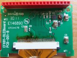
    NIVONA Caferomatica 830 Coffee Machine: Damaged Display Repair, AliExpress Replacement

    and here the coil
    NIVONA Caferomatica 830 Coffee Machine: Damaged Display Repair, AliExpress Replacement
  • #237 18425531
    amigos
    Level 16  
    The coil should not cause problems. According to me, first of all, you should thoroughly wash the rosin plate to look at the paths. The pins are hard to desolder and it is easy to break off the paths and break out the rings connecting both sides of the plate. You have to watch them carefully from both sides. I enclose a photo of the bare original tile. Check with a meter whether the paths have a pin socket on both sides. I think you have a problem there. The tin is on one side of the soldering of the pin socket, and the paths on the other side coming out from under the socket due to the torn rings depend on whether the pin touches the path or not. If so, bridge the path with the pin where there will be no good contact. Meter in hand and short cables ;)
  • #238 18439234
    dzako071
    Level 8  
    as if someone was interested, I have to give away at cost a few complete sets of elements together with clean pcb according to the designs of Amigosa and Satanistik. I also add a connector. info on priv
  • #239 18452650
    badsipsik
    Level 1  
    Hey guys,
    ordered tiles from Satanistiks design, also ordered OLED from aliexpress (aliexpress.com/item/33027229991.html?spm=a2g0s.9042311.0.0.61be4c4dIjVSUx).
    Its turned out, that in product name it is SPD0301, but in reality SSD1309.

    Soldered-assembled, but when trying to connect new display assembly with coffemachine - nothing happend (also no initialization). If to connect new tile, but without display connected - then machine starts.

    Any ideas? Could the problem be in that display is SSD1309 and it is not suitable for satanistik design?
    Green printed circuit board with an attached OLED display and electronic components.

    P.S. R4 replaced with 120 kΩ and missing GND bridge from IC1 aslo added.

Topic summary

The discussion addresses the issue of a damaged OLED display in the NIVONA Caferomatica 830 coffee machine, with the original replacement cost around PLN 900-1000. Users confirm the original display uses the SSD1303T10 driver and is a 128x64 pixel OLED module with a 31-pin connector, which is now rare and discontinued. Attempts to find direct substitutes on AliExpress or other markets largely failed due to incompatible controllers, pin layouts, or mirrored image outputs. Alternative displays such as BL12864G (yellow OLED) from SOS electronic (Slovakia) and similar models from Japan or Russia have been used successfully but require delicate desoldering and soldering of the 31-pin ribbon cable, a process recommended only for skilled technicians. Some users developed or are developing adapter boards to use newer SSD1305, SSD1309, or SPD0301 controller displays, which have different pinouts and may show mirrored images or missing columns, requiring hardware or firmware adaptations. The community shares detailed disassembly instructions for accessing the display module, emphasizing careful removal of the front panel and soldering challenges. Some users report successful repairs by cleaning pins or replacing capacitors and diodes on the motherboard. The discussion also highlights the scarcity of original or compatible displays, the need for specialized repair skills, and ongoing efforts to create adapters for newer OLED modules to extend the machine's lifespan.
Summary generated by the language model.
ADVERTISEMENT