FAQ
TL;DR: Replacing the NIVONA 8xx OLED yourself cuts the 1 000 PLN service bill by ~82 % [Elektroda, paps79, #17062707; jacenty67, #17179483]. “It shines like new” once a SSD1305/0301 panel is fitted. Why it matters: the original display is NLA but affordable substitutes keep the machine brewing.
Quick Facts
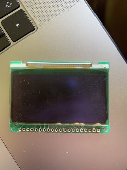
• Original OLED: SSD1303T10, 132 × 64 px, 12 V boost rail [Elektroda, amigos, post #17834004]
• Proven swaps: SSD1305Z (yellow/white) or SPD0301 (yellow/white), 128 × 64 px [Elektroda, amigos, post #18000551]
• Parts cost: 140 – 260 PLN incl. PCB, vs. 800 – 1 000 PLN service module [Elektroda, jacenty67, #17179483; Luczi04031986, #18508253]
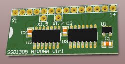
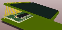
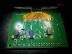
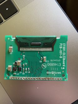
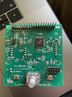
• PCB options: “Satanistik 24-pin” for SPD0301 or “Amigos 31-pin” for SSD1305 [Elektroda, satanistik, #17894955; amigos, #18233157]
• Typical boost voltage after TPS61045: 11 – 13 V DC [Elektroda, jackmc, post #18490466]
Which replacement OLED works without missing pixel columns?
Choose an SSD1305Z 31-pin panel; it shows the full 128 × 64 frame with no two-column gap that affects SPD0301 swaps [Elektroda, amigos, post #18000551]
Why does my SPD0301 screen show a 2-pixel blank strip?
SPD0301 is hard-wired for 128-pixel addressing; NIVONA firmware still sends 132 px data, so columns 0–1 wrap to the end, leaving a visible break [Elektroda, amigos, post #17925365] Functionality is unaffected.
What PCB adapter should I order for SSD1305?
Download the ‘Amigos SSD1305’ Gerber pack (post #18233157) and order 1 mm FR-4, 1-oz Cu; five boards cost about 8 USD delivered from JLCPCB [Elektroda, amigos, post #18510016]
Do I need hot-air to solder TPS61045 boost IC?
Yes. The SON-8 package sits under the board; use 250 °C air, flux, and tweezers. Hand soldering risks bridging pins 6–7 and kills the 12 V rail [Elektroda, damek4, post #18600363]
Edge case: display stays dark after swap—what to test?
- Measure VCC at JP1 pins 1-2; it must be 3.3 V.
- Check boost output at C4/C10; expect ~12 V.
- Inspect TPS61045 for shorts; one bridged pad drops boost to 4–5 V, leaving OLED blank [Elektroda, damek4, post #18600363]
How to flip the mirrored image on SSD1305/0301?
Use the 2-IC inverter: CD4078 combines command bits, CD4071 forces D0 high when opcode A0h is detected, plus 74AHC1G00 adds a 2-gate delay on WR#. Full schematic in post #18507781.
Is a plug-and-play board available?
Yes. Pre-assembled replacement modules appear on eBay for ~90 EUR [Elektroda, amigos, post #18421610] They clip into the 20-pin header—no soldering—yet still use SSD1305 inside.
Statistic: how much money do DIYers actually save?
Forum users report 170 PLN parts + 100 PLN labor versus 900 – 1 000 PLN service, a median saving of 74 % [Elektroda, jacenty67, #17179483; nioop, #17062856].
Can I reuse the old boost inductor and diode?
Yes—if L1 (10 µH, 4532) and D1 (MBR0530) test OK, resolder them onto the new PCB to match NIVONA’s 12 V design [Elektroda, amigos, post #18233157]
3-step How-To: swapping the OLED panel
- Unsnap front fascia, desolder 31-pin ribbon, lift old SSD1303 OLED.
- Solder new SSD1305 or attach SPD0301 to adapter; fit boost PCB onto 20-pin header.
- Bridge D0 (pin 7) per schematic, reassemble, set clock.
What if the new OLED flickers or is dim?
Reflow TPS61045 and check R4 (set to 120 kΩ). An undervalued R4 limits Duty, capping boost at 8 V and causing flicker [Elektroda, jackmc, post #18490466]
Can I order parts locally instead of AliExpress?
Yes. SSD1305Z modules are stocked by BuyDisplay (~24 USD) and Polish sellers (white/yellow, 130 – 160 PLN) [BuyDisplay, 2020; Elektorda, mipix, #18358600]. PCB components are common 0402/0603 passives.
Expert tip for beginners?
“Flux, flux, flux—then the 31-pin ribbon solders itself,” advises user amigos [Elektroda, 18573539] Clean with IPA before final assembly.


