logo elektroda
logo elektroda
X
logo elektroda

NIVONA Caferomatica 830 Coffee Machine: Damaged Display Repair, AliExpress Replacement

paps79 276486 462
ADVERTISEMENT
Treść została przetłumaczona polish » english Zobacz oryginalną wersję tematu
  • #301 18600363
    damek4
    Level 11  
    I converted the TPS chip and now the screen is black. I measured the output voltage and it is 4.9V, I could damage the display.

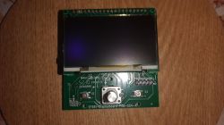
    Close-up of a circuit board with a TPS unit and electronic components after soldering.
  • ADVERTISEMENT
  • #302 18600451
    amigos
    Level 16  
    How did you solder? I don't know what your soldering skills are. To be honest, for me these elements on the plate look terrible. Wash it from the flux to see something :) Check whether there are short circuits between the TPS legs, because often under the system, if you give too much tin before soldering, a short circuit may arise with inefficient soldering. You will have a short circuit between legs 6 and 7 and 1 and 8 with the coil mounted. If you were warming up with a hotair, I hope you have peeled off the display, because if you heat it too much, the display will fall. You will see it after discoloration. If you have a weak soldering, give someone to do it, because you need some skills for TPS.
  • #303 18622068
    redzid
    Level 11  
    @Smoczy
    Hello, I was very interested in your project with the 39VF512 chip.
    You write that this integrated circuit has modified content so that you can "pass" WR signal through it. I do not understand it very much, whether you have modified this content yourself, or just simply buy this SST39VF512-70-4I-WHE system, e.g. from the TME store and it will be good.
    greetings
  • #304 18622221
    Smoczy
    Level 19  
    The system must be programmed. The content was created by me.
  • #305 18622248
    satanistik
    Level 27  
    Content can be created in any hex edit program. Enter its address in each cell, e.g. in 0h 0h in 1h 1h, except for the cell that corresponds to the scan direction command, where we change one bit. Required knowledge of binary code, can be converted to hex, e.g. with a Windows calculator. The WR signal delay is that it passes through the memory with the same delay as the rest. The issue to read are combination machines on eprom memories.
  • ADVERTISEMENT
  • #306 18622273
    redzid
    Level 11  
    OK thanks. I thought you had already bought programmed. However, I can't handle programming. greetings
  • #307 18633637
    amigos
    Level 16  
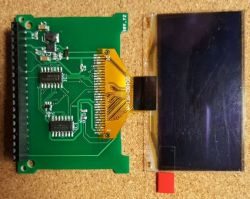
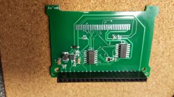
    I received the tiles according to the J4rek design and finally found time to test the variant without TPS. For me a revelation, everything goes without a problem. Below photos.
    It is known that the board must be desoldered on a 20-pin connector from the control board to be able to desolder the old display and solder the new one. Move the plastic bridge connecting the pins as high as possible and bend pins 5 and 7 to fit the holes in the J4rek board. Slide the board onto the pins and solder also soldering 2 missing pins to the controller board. Cut out protruding elements and solder the whole joint in its place. Display ready ;) As a capacitor C1 I gave 4.7uF, and as C2 and C3 I gave 100nF. I haven't tested the TPS board yet.

    NIVONA Caferomatica 830 Coffee Machine: Damaged Display Repair, AliExpress Replacement NIVONA Caferomatica 830 Coffee Machine: Damaged Display Repair, AliExpress Replacement NIVONA Caferomatica 830 Coffee Machine: Damaged Display Repair, AliExpress Replacement NIVONA Caferomatica 830 Coffee Machine: Damaged Display Repair, AliExpress Replacement NIVONA Caferomatica 830 Coffee Machine: Damaged Display Repair, AliExpress Replacement
  • ADVERTISEMENT
  • #308 18635016
    j4rek
    Level 19  
    Hello, it's great that the design has been checked and works properly. C1, C2, C3 can all be 100nF.

    I have a faster (maybe less aesthetic) way to disassemble both tiles - cut the original ladder 'pin by pin' with sharp cutters in about half the length.

    We unfold the plates and replace the display with a new, cut pin 5 and 7 from the display plate remove and clean their assembly points. You can also slightly shorten these pins and solder to them after folding the wires from points X1.5 and X1.7.

    I need to solder 2 longer pins / wires of silverware (to X1.5 and X1.7) into my plate, properly shaped so that after applying and soldering they fit nicely into the exact upper plate with the display. After assembling the whole, we solder the breaks created when cutting the ladders and soldering points 5 and 7 on the display board.
  • #309 18635792
    j4rek
    Level 19  
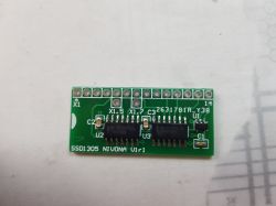
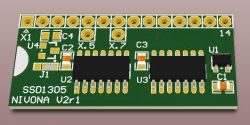
    I place a newer version of the board (V2r1)

    - the previous arrangement of connections in the gates has been restored (this has been verified, however, this does not affect the operation)

    - the option of mounting the LDO 3V3 stabilizer (U4) powered from Vbat has been added

    - on the left side is marked and drilled area, which after breaking should allow to bypass the dowel from the black base

    View of SSD1305 NIVONA V2r1 PCB with electronic components.

    Diagram and gerberas attached.
  • #310 18636985
    amigos
    Level 16  
    Somehow it is easier for me to solder in this way

    Close-up of a green circuit board with soldered pins. Circuit board with soldered pins and visible traces.
  • #311 18644026
    quatschei
    Level 1  
    Hi,
    Where can I find the tps chip?
    It was said that you could remove it from the old board (U1), but I only have a U2 chip with 10 legs.
    But you need a chip with 8 legs.
    Use amigos board with SSD1305.

    Thank you very much
  • #313 18650989
    dekRe
    Level 15  
    Hello!
    The J4rka solution looks brilliantly simple - congratulations, so when it works with SSD1305 in addition - it's a design revelation and full of professionalism!

    I only have questions
    1. JP1 jumper with 2.7V and 3.3V voltage selection - what should be the voltage selection for SSD1305 - or are there SSD1305 with different voltages?
    2. I prefer to be sure just in case, so I will ask here - if the CD4078BM DIGITAL BILATERAL SWITCH SOP-14 E4702
    or from the same seller the second system marked as CD4078BM DIGITAL NOR CMOS SOP-14 E4701
    are the same systems as the CD4078B NOR / OR marked on the diagram and can be used interchangeably in this project?
    Thank you for this project and best regards
  • #314 18652585
    j4rek
    Level 19  
    1. By default, you set the jumper on 2V7, and U4 and C4 are unnecessary. This is an option as if the systems have a problem with stability at 2.7V power supply. Theoretically, according to the documentation, they have a minimum 3V guaranteed.

    2. The most important designation is CD4078BM. Generally, the system has the designation CD4078B, and the letter M at the end indicates only the type of housing (SOP-14).
  • #315 18653741
    kris6661
    Level 11  
    Do you know the store where to buy IC 2 and IC 3? I can't get them anywhere. 4078D and 74AHC.
  • ADVERTISEMENT
  • #316 18654541
    j4rek
    Level 19  
    SN74AHC1G00DBVR and CD4078BM are available at tme.eu.
  • #318 18677595
    Savik
    Level 13  
    Hello high class specialists :)

    At the beginning I wanted to announce that it is quite pleasant to read here :)

    I allowed myself to write here because many specialists follow the thread. To the point. In my new used 831 the display fell, but in a very strange way. First there was a problem with making latte, after a few coffees error 9, a few minutes off and continued to work. When such a mistake appeared more often, I once gently tapped the mobile terminal and then everything went on. The guest from whom I bought said to remove the module, remove the plugs and insert again. I did it, put it together, turned it on, made coffee, I say okay. After next switching on it was a standard screen, then before I could choose anything, it turned 180 degrees and everything disappeared, no reaction to the buttons. After switching off and on with the on / off switch on the side, nothing appeared on the screen anymore, no reaction to the on button at the top. I have to understand that the display module to be replaced? I will add that only after switching on you can hear the sound of the power supply inside and that's it.

    The second thing, apparently the screen was replaced recently ... should this be what solder connections should look like after replacement? It looks like a factory to me ...
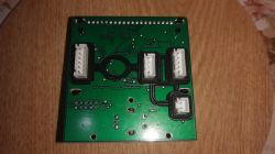
    NIVONA Caferomatica 830 Coffee Machine: Damaged Display Repair, AliExpress Replacement NIVONA Caferomatica 830 Coffee Machine: Damaged Display Repair, AliExpress Replacement

    Added after 6 [hours] 56 [minutes]:

    Or maybe someone is in the area of Kielce / Radomsko - Końskie - Częstochowa to come with him, change the display and check if it is really that fault?
  • #319 18679490
    j4rek
    Level 19  
    Damage to these displays is mainly manifested as burnout - poor visibility, and your fault is rather some errors in the driver or communication between components. It is possible that there is some cold solder in the display module (pcb with microprocessor). It is advisable to replace it with another module to exclude it.

    For model 831 I found a description of error 9 (translated from German):

    Meaning: Engine valve error, device malfunction.

    Cause: Damaged drive motor valve, valve not in (zero) position.

    Source:

    https://www.jura-ersatzteile-shop.de/document...ce_Anleitungen/Hinweise/nivona-error-code.pdf
  • #320 18679570
    Savik
    Level 13  
    Thank you for your answer

    I wrote an e-mail to the nivony service, which seems to indicate a ceramic valve. Which engine can this apply to? Brewer or ceramics?
  • #321 18723753
    damek4
    Level 11  
    Hello, where can I get the TPS61045DRBR U1 SON-8 TEXAS INSTRUMENTS?
  • #323 18724342
    Savik
    Level 13  
    In my abovementioned 831, which I returned to the service I bought from, the display board fell, although I do not know exactly what was there but she was the culprit, no communication with the motherboard, because the motherboard was good. The espresso machine came back to me and brews delicious coffee :)
  • #324 18739702
    ketchup007
    Level 10  
    Hello,

    Does anyone have a redundant SSD1305 display board for resale?
    I ordered all parts and tiles of the @satanistik project ... and as it came, it turned out that it was not what I had ordered :)
    Will anyone help? because aiming coffee in the dark is almost a miracle :D
    And what if, I have a few pieces of free project @satanistik ... If someone needs to send it.

    greetings
  • #325 18750031
    mjdob
    Level 1  
    Hello,
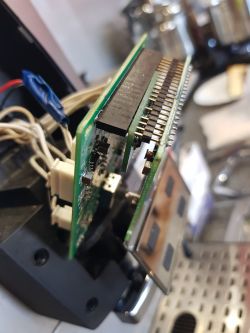
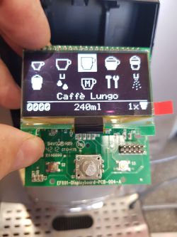
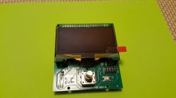
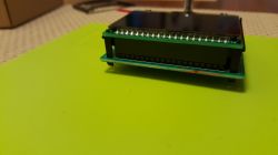
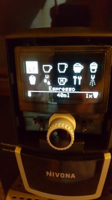
    I would like to begin by thanking the authors of the solutions saving the display module for their work input and sharing projects with other users. First of all, my thanks go to amigos, because it was on his design that I carried out the display replacement. Probably soldering could always be a bit nicer, but the screen fired without any corrections and glows, it's nice. The tile was perfectly matched, entered the factory place on the stand and looks like the original. I left the pin connector original, while I soldered the socket into the display board (in case of disassembly and making corrections). Fortunately, there were no corrections, and the female pin connector fits perfectly in height. The whole looks like the pictures. Amigos, thank you very much again.

    Electronic board with a display module after installation A circuit board with integrated circuits and a pin header on a cork surface. Shown is a display module mounted on a PCB with a green background. Close-up of a display module mounted on a green connector board. Display of a Nivona coffee machine showing the menu and selection of 40 ml espresso.
  • #326 18750119
    amigos
    Level 16  
    Cool. I am glad that the work inserted in this topic is appreciated and its effects used. As we created projects, there was probably no public solution available on the market. There are quite a few now ;) I think that many machines were saved.
    The tile came out very nice for you.
    Greetings.
  • #327 18766318
    volkeri
    Level 2  
    Hello everyone,
    I soldered three circuit boards and none of them worked. I do not know what I'm doing wrong.
    I have inserted the pictures of the last board.
    Where can I measure something?

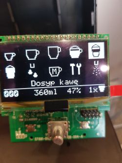
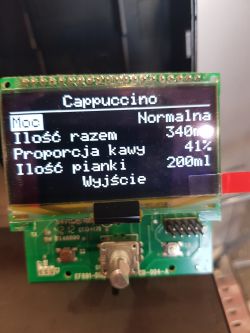
    NIVONA Caferomatica 830 Coffee Machine: Damaged Display Repair, AliExpress Replacement NIVONA Caferomatica 830 Coffee Machine: Damaged Display Repair, AliExpress Replacement NIVONA Caferomatica 830 Coffee Machine: Damaged Display Repair, AliExpress Replacement
  • #328 18767796
    slawek2901
    Level 2  
    Hello
    I ordered this display
    BL 12864G2 ERNHn BOLYMIN
    BL 12864G2 ERNHn
    and I wonder if it will match the NIVONA express.
    It turned out that the tape has only 24 pins.
  • #330 18768631
    damek4
    Level 11  
    I will buy some complete display repair project, maybe someone has something in excess.

Topic summary

The discussion revolves around the repair and replacement of the display for the NIVONA Caferomatica 830 coffee machine, which often suffers from display failures. Users share experiences with sourcing replacement displays, particularly the SSD1305 and SPD0301 models, and the challenges of soldering and adapting new displays to the existing circuit boards. Various solutions are proposed, including using a custom PCB designed by community members, which allows for the integration of new displays while addressing issues like image mirroring. Participants also discuss the necessary components for the repair, including capacitors and integrated circuits, and share links to suppliers for parts. The conversation highlights the collaborative effort to find effective solutions for display issues in NIVONA machines.
Summary generated by the language model.
ADVERTISEMENT