logo elektroda
logo elektroda
X
logo elektroda

Fibaro control of Rain Bird 100-HV solenoid valve - coil heats up

alarec 5523 33
ADVERTISEMENT
Treść została przetłumaczona polish » english Zobacz oryginalną wersję tematu
  • #1 17818608
    alarec
    Level 11  
    Hey,

    I have this quick question about controlling the solenoid valve with a fibaro double switch.
    The fibaro module is a simple relay connected to 230V
    specification: https://manuals.fibaro.com/pl/single-double-switch-2/

    The electro-valve on the other hand is:
    Rain bird 100-hv
    specification: https://instalhurt.sklep.pl/Elektrozawor-100HV-Rain-Bird-przelotowy-1-GW

    The electro-valve is connected via a 24V power supply, o such:
    https://allegro.pl/oferta/zasilacz-impulsowy-24v-1a-led-stabilizowany-6865885234

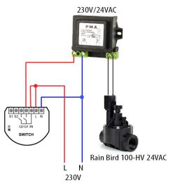
    Everything works great, you can control the solenoid valve, it opens, closes, but the solenoid from the solenoid valve even when at rest heats up quite a bit - this is rather not normal.
    I assume I used the wrong power supply, the solenoid valve is under VAC and the power supply is probably VDC am I right?

    What power supply would be best for this configuration? Can you guys recommend something? (Ultimately it will operate 5 solenoid valves, but of course they will not be switched on at the same time ever)
  • ADVERTISEMENT
  • #2 17818666
    sosarek

    Level 43  
    alarec wrote:
    I assume I used the wrong power supply, the solenoid valve is under VAC and the power supply is probably VDC am I right?
    .
    Yes, you are correct.
    alarec wrote:
    What power supply would be best for this configuration?

    24VAC with a capacity equivalent to 5 valves i.e. 5x0.25A=2.25A. So a 24V power supply(actually a transformer) with a capacity of 3A will be sufficient.
    Helpful post? Buy me a coffee.
  • #3 17818852
    alarec
    Level 11  
    correction 5x0.25A=1.25A
    but the resting capacity is 0.14, so assuming that 4 are maintaining and one is currently working, it seems to me that 4*0.14 + 0.25 = 0.81A should be enough ?

    ... .

    could you send something else up to a maximum of 50zł ?

    Please do not post links to auctions - temporary nature of link //kozi966 .
  • ADVERTISEMENT
  • #4 17818947
    sosarek

    Level 43  
    alarec wrote:
    correction 5x0.25A=1.25A
    .
    Fact, I haven't had my coffee yet.
    Take into account that this is the inrush current and can be higher - the power supply is selected with an allowance so 2A will be ok.
    Zamel is out.
    Helpful post? Buy me a coffee.
  • ADVERTISEMENT
  • #7 17868888
    alarec
    Level 11  
    sosarek, I didn't go to school, I'm self-taught. But I've already managed.

    However, I ordered and connected this P.M.A trafo and on it the solenoid valve buzzes terribly (and quite loudly).

    At the output of the trafo exactly 27.8V

    So this won't fit either, then?
  • #8 17870112
    jack63
    Level 43  
    alarec wrote:
    At the output of the transformer exactly 27.8V

    So that won't fit either though?
    .
    If this is the no-load voltage, then you can safely connect.
  • #9 17870672
    alarec
    Level 11  
    In addition, to check, I gave a KBL06 bridge from the traf.
    The buzzing has stopped, the coil is not overheating and the valve is opening.
    It seems to be working fine.

    Can it stay like that or do I need to enrich such a circuit with something? Any additional capacitors?
  • #10 17870714
    jack63
    Level 43  
    And why did you give a rectifier bridge?
    After all, it's enough to power the valve coil through the relay directly from the transformer.
    The parameters of the valve coil clearly state 24VAC, or alternating current from a 24V rms source.
    With AC voltage, less current flows through the coil winding than with rectified voltage and even less than with DC voltage.
    These are the basics of electrical engineering....
  • ADVERTISEMENT
  • #11 17871083
    alarec
    Level 11  
    I.e. The point is that on the transormator itself (from the transformer directly to the coil) the valve makes a terrible noise.
    Exactly it is a sound like the one in this video:
    https://youtu.be/In66dttmOs8

    And I want to eliminate it.
    With the bridge it is quiet, but as I hear it now it is not a correct combination. So how to get rid of this sound?
  • #12 17871173
    starob
    Level 29  
    It could operate at DC, the strength of the electromagnet is determined by the amperage. For a current rating of 0.15-0.25A and a resistance of 55ohm this power supply could be about 12VDC. However, it may not work because of the design of the electromagnet core (which we do not know), at DC the anchor may 'stick and the valve may not close.
    So much theory... Connect this valve to the system and I assure you that under pressure nothing will buzz. I use exactly the same valves and power them from a 24VAC tray and nothing buzzes.
    In such valves, the solenoid does not directly control the "gate" but only opens some nozzle with a small force and the water pressure does all the mechanical work.
  • #13 17871213
    alarec
    Level 11  
    I will check today how it is under water pressure.
    I'll connect directly to the trafo - I have the ones I listed above: https://uk.rs-online.com/web/p/current-transformers/7457995/

    I hope it settles down, because so far I've only switched on for a while in this configuration because I was afraid it would burn up.
  • #14 17871607
    jack63
    Level 43  
    Nothing should burn up with a transformer supply, or maybe with other combinations.
    Trying with a dry valve makes no sense. It's a pilot operated solenoid valve, which means it's indirect acting. Most of the work is done by pressurised water. The solenoid valve itself (pilot) only opens tiny "holes" into which the water is supposed to flow and do the rest of the work, i.e. close or open the main flow.
    Watch out for the direction of the main flow. There should be an arrow on the body indicating in which direction the water should flow. Switching it on the opposite way results in no valve operation. The flow is all the time!
  • #15 17871859
    alarec
    Level 11  
    He understands that if, for example, they turn off the water and the solenoid valves are switched on for, say, 30 minutes, they are also safe?
  • #16 17871931
    jack63
    Level 43  
    No, although it is better to read the valve documentation to see if there is a loophole. For example, "for casual work" etc. etc.
    A normal valve should be able to be turned on 24/7/365.
    The only danger is dirty water, for which it is 100% not designed. It is a good idea to give a mesh filter somewhere in front of it.
  • #18 17872892
    starob
    Level 29  
    alarec wrote:
    according to me it runs too loud.
    ..until I checked with myself and found mine to be confusingly similar to the Rain RN 150. Without pressure it is silent.
    At the moment you are definitely powering correctly and if the coil doesn't heat up then use it.
    You can continue to speculate about the causes, but if it works, doesn't heat up and it doesn't bother you then there is no point. To be sure, you can measure the coil current to see if it is within the rated limits.

    In this video, are you controlling the Fibaro Switch (the black thing in front of the transformer)? - It is not for inductive loads.

    Added after 16 [minutes]: .

    alarec wrote:
    The fibaro module is a simple relay connected to 230V
    it may not be a simple relay but a triac.
  • #19 17873018
    jack63
    Level 43  
    starob wrote:
    may not be a regular relay but a triac.
    .
    This is also my opinion. This can be ruled out by connecting the valve coil directly to the tranformer.
    Another possibility is that the valve is too large in relation to the flow occurring and is vibrating. Such valves require a sufficient pressure drop between input and output to sustain an open state.
  • #20 17873188
    alarec
    Level 11  
    starob wrote:
    Do you control via Fibaro Switch (black thing in front of the transformer) in this video? - it's not for inductive loads.

    Fibaro Switch, connected to the mains, and from it to the transformer, so this is probably the correct connection ? (I have included a diagram below)

    jack63 wrote:
    This can be ruled out by connecting the valve coil directly to the tranformer.
    .
    I also connected the trafo directly to the mains (excluding the fibaro), same situation.

    jack63 wrote:
    Another possibility is that the valve is too large in relation to the flow occurring and is vibrating. Such valves require a sufficient pressure drop between the input and output to sustain the open condition.
    .
    While the valve was open I also adjusted the pressure - this had no effect on the solenoid / solenoid operation.

    I am posting a diagram of how I have it wired now:
    Fibaro control of Rain Bird 100-HV solenoid valve - coil heats up .

    And do you think it will work the same way with a Hunter 100-PGV valve? Because that's what I'm planning to buy in the near future.
  • #21 17873202
    starob
    Level 29  
    If this is true, it is even worse in the video - the transformer is powered by this "relay" ( ...that it works at all?!! :) ) .
    Therefore, the valve is powered with no idea what voltage. Ultimately, the author has a problem to "couple" it all together. With more valves there will be one transformer, and each valve must be controlled by a separate "real" relay. I couldn't find anything in the Fibaro range that would be suitable.

    Added after 6 [minutes]: .

    Extract from the Fibaro manual
    The connected load and Switch 2 itself may be damaged if the load does not comply with the technical specifications!

    The following rules must be observed when connecting Switch 2:

    Do not connect loads larger than those recommended!
    Do not connect loads other than resistive or incandescent loads!

    This contact drawing is only symbolic. Your connection is absolutely correct, but for control the "relay" is inadequate.

    Added after 4 [minutes]:

    Perhaps the coil has already been battered with DC voltage early on.
    Describe a bit more about how you want it to look as a whole target then something will work out.

    Added after 3 [minutes]:

    Any valve is suitable if you apply it correctly.

    Added after 11 [minutes]:

    Consider buying the Rain Bird ESP-RZXe 6, the complete controller is the price of one Fibaro Switch.
    By expanding with WiFi you have the ability to control from your smartphone.
  • #22 17873432
    alster1
    CCTV and Stationary Alarms specialist
    alarec wrote:
    And do you think it will work the same way with a Hunter 100-PGV valve? Because this is what I intend to buy in the near future.
    .
    I have an irrigation done at my place on Hunter 100-PGV valves (10 sections - 10 valves), AC supply from an ordinary 24V transformer via relays, this is controlled by a control panel. It has been running smoothly for 5 years now, nothing buzzes, the valve only makes a quiet click when the power is switched on.
  • #23 17873435
    alarec
    Level 11  
    I have a fibaro switch version 1 acct (https://manuals.fibaro.com/double-relay-switch/), I don't know if there is any difference.
    or this one ( https://manuals.fibaro.com/content/manuals/pl/FGS-221/FGS-221-PL-A-v1.02.pdf ) I can't remember now
    According to the instructions its load:
    Quote:
    6.5A (up to 1.5kW) per channel for resistive load, but the total load must not exceed 10A
    .
    so it is not exceeded

    starob wrote:
    Describe something more about how this is supposed to look in total target then something will come up.

    Ultimately, there are to be 2 fibaro double switch units, which will control 4 electro-valves (so far I have 1) - that is 4 sections for watering.
    And nothing else, i.e. just turn the corresponding solenoid valve on/off.

    starob wrote:
    Consider buying Rain Bird ESP-RZXe 6, the complete controller is in the price of one Fibaro Switch.
    By expanding with WiFi you have the ability to control from a smartphone.

    Controller + wifi + precipitation sensor + wind sensor + temperature sensor adds up to over 1000£ so it's quite an expensive investment.
    I currently have a few spare fibaro devices, including switches. There are already outdoor/indoor temperature sensors, precipitation sensor and wind meter on the roof connected to the system, so now just connecting fibaro relays/triacs to the electro-valve I have no costs. All I need to do is write the appropriate scenes, dependent on temperature, humidity, wind, time of day and in theory everything should work.
  • #24 17873438
    alster1
    CCTV and Stationary Alarms specialist
    Will you be giving a separate transformer to each valve controlled by Fibaro?
  • #25 17873462
    alarec
    Level 11  
    No - one for all.
    And so the sections switch on independently one after the other, never more than one valve.
  • #26 17873472
    starob
    Level 29  
    alarec wrote:
    I have fibaro switch version 1 acct (https://manuals.fibaro.com/double-relay-switch/), don't know if this makes any difference.
    .
    That changes things :) Your first link pointed to something else.
    On this one you will be able to control the valves from a single transformer.
    The switch has a potential-free contact, so there will be no problem with controlling the valves after 24VAC.
    As for the buzzing, it's either the beauty of it or you've damaged the coil with DC.
  • #27 17873478
    alster1
    CCTV and Stationary Alarms specialist
    alarec wrote:
    No - one for all.
    And so the sections switch on independently one by one, never more than 1 valve.
    .
    OK, just check that the fibaro control outputs are definitely isolated from the mains (potential-free). If they are then this should work.
  • #28 17873597
    alarec
    Level 11  
    alster1 wrote:
    OK, just check that the fibaro control outputs are definitely isolated from the mains (potential-free). If they are then this should work.
    .
    Will some diodes + resistor suffice or do you suggest any other solution?
  • #29 17873623
    starob
    Level 29  
    alarec wrote:
    Will some single-ended diodes suffice or do you suggest some other solution?
    .
    Excess information can be fatal :) .
    Potential-free i.e. there is no connection between the L and IN terminals
    Do not combine and connect
    To the fibaro and transformer only LN 230v.
    To the valve - 24v from the transformer via terminals IN-Q1 in series (do not make a bridge between L-IN !!!)
    To be sure, after connecting, check with a neon lamp if you have no mains voltage on terminals IN,Q1,Q2
    Draw the diagram as you understood it
  • #30 17873646
    alster1
    CCTV and Stationary Alarms specialist
    This Fibaro module seems to have a measurement of the energy consumption of the receiver, meaning these outputs are not quite so clean, this plan with 24V may not work.

Topic summary

The discussion revolves around controlling a Rain Bird 100-HV solenoid valve using a Fibaro double switch relay connected to a 230V power supply. The user reports that the solenoid coil heats up excessively, raising concerns about the compatibility of the 24V power supply, which is likely DC, with the valve designed for 24VAC. Participants suggest that a transformer with a capacity of at least 3A is needed for five valves, and emphasize the importance of using AC power to avoid overheating and buzzing noises. The user later connects a rectifier bridge, which alleviates the buzzing but raises questions about the appropriateness of this setup. The conversation also touches on the need for proper isolation of the Fibaro switch outputs and the potential for using a single transformer for multiple valves. Ultimately, the user seeks to ensure safe and effective operation of the irrigation system.
Summary generated by the language model.
ADVERTISEMENT