logo elektroda
logo elektroda
X
logo elektroda

BK7231N SmartPlug (Aliexpress 1005007884300347) Flashing Pinout Identification

blacksun2 369 12
ADVERTISEMENT
  • #1 21592558
    blacksun2
    Level 7  
    Hello,

    I bought a SmartPlug from Aliexpress with metering.
    At the moment, the device is a Tuya-Device and I want to flash openbeken.
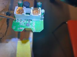
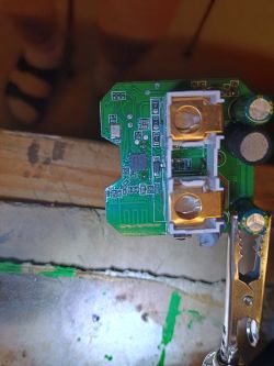
    The Device has a BK7231N Chip. The board has 6 soldering points, but these points are not named.
    The Points do not fit the BK7231N-Layout at all.
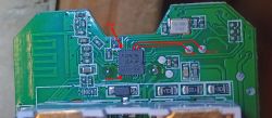
    BK7231N SmartPlug (Aliexpress 1005007884300347) Flashing Pinout Identification

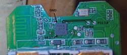
    BK7231N SmartPlug (Aliexpress 1005007884300347) Flashing Pinout Identification

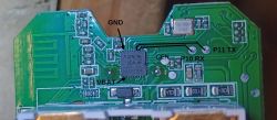
    BK7231N SmartPlug (Aliexpress 1005007884300347) Flashing Pinout Identification

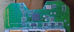
    SmartPlug PCB with six unnamed soldering pads next to the BK7231N chip.

    Where do I have to connect to for flashing?

    Big thanks

    AI: Can you provide the exact model number or a link to the Aliexpress listing for your SmartPlug?
    https://de.aliexpress.com/item/1005007884300347.html
  • ADVERTISEMENT
  • #2 21592984
    max4elektroda
    Level 20  
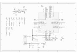
    If I interpret the pictures correctly, you need to use Pins 26 and 27 (26=P10=RX / 27=P11=TX).
    They seem connected to the two pads below the quartz.

    You need to connect RX of chip to TX of your serial and TX of chip to RX of your serial.

    Either have a powerful 3.3V power supply or you can try if the device works, if you connect a power supply of 12V or 15V directly to the mains contact (so instead of using high voltage like 230V try if it works with a much lower voltage).
    In almost all devices the 3.3V or GND of the board is connected to one of the mains contacts, so never connect serial if it's connected to live power!


    BK7231N SmartPlug (Aliexpress 1005007884300347) Flashing Pinout Identification

    Hope this one is readable:
    BK7231N SmartPlug (Aliexpress 1005007884300347) Flashing Pinout Identification
  • #3 21593130
    blacksun2
    Level 7  
    >>21592984

    du meinst ich soll über die Stecker, die in die Steckdose kommen, 12V Gleichstrom anlegen? Das soll funktionieren?
    Ist es dann egal, ob welcher Stab + und - reingehen?

    Was mir dann aber immer noch fehlt, das ist der Reset-PIN
  • #4 21593188
    max4elektroda
    Level 20  
    Genau, irgendein Netzteil mit ungefährlicher Spannung, je höher desto besser. Da der Stecker für Wechselspannung ist, ist es bei einer Gleichspannug egal, wie die angeschlossen wird. Ist auch nicht gesagt, dass es funktioniert, aber bei einigen meiner Steckdosen funktioniert das problemlos.
    CEN ist der vierte von oben rechts, da ist auch ein Pad zu sehen, etwas links unterhalb des RX Pad, direkt neben den zwei SMD Bauteilen.


    Close-up of a PCB section with four pins on the right and two SMD components next to one pin.

    Da wir hier im Internationalen Bereich sind:
    Exactly, no guarantee it works, but I have several plugs that work that way, i usually use an old 19V Laptop power supply.
    Since the plug is working with AC, polarity doesn't matter.
    The CEN pin is the 4th pin from top on the right in your picture, near to the two smd parts.
  • ADVERTISEMENT
  • #5 21594329
    blacksun2
    Level 7  
    >>21593188
    ich hab mal ein 600Watt-Netzteil rausgesucht mit dem ich eine 12V-Pumpe betrieben habe. Die blaue LED ist tatsächlich angegangen.
    sich per Netzwerk verbunden hat sich die Steckdose aber nicht. Vielleicht war es zu wenig Spannung.
    Auf RX und TX war nichts zu erreichen.
    Wie merke ich, ob es funktioniert?
  • ADVERTISEMENT
  • #6 21594354
    max4elektroda
    Level 20  
    Vielleicht reichen die 12 V nicht. Das Gerät sollte damit normal arbeiten, wie in der Steckdose: entweder meldet es sich im WLAN an, oder arbeitet als Access-Point. Leuchtet die LED normal hell oder funzelt die nur leicht?
    Es gibt auch eine log Schnittstelle, das ist aber der Kontakt oben, der nicht verbunden scheint. Du brauchst dann einen Nadelkontakt, um das abzugreifen.
    Wenn es nicht funktioniert, könntes du eine höhere Spannung verwenden, falls du ein anderes Netzteil hast.
    Ansonsten musst du direkt die 3.3 V anschließen. Dafür benötigst du zum einen ein gutes Netzteil und solltes vielleicht noch ein paar mehr Detailfotos hochladen, damit man den Spannungswandler findet oder zumindest Punkte, wo man die Spannung gut einspeisen kann.

    Maybe 12V are simply not enough for your plug.
    It should work like usual, connect to your network or act as an access point. Is the led fully on or just glowing?
    You should also be able to see serial logs, but TX for the logs is the unconnected pin in the upper row, so you would need to connect it per needle to see output.
    If you don't see the plug in your network, you might try a higher voltage, maybe you have another power supply?
    If not, you will need to power the 3.3 rail, maybe some more detailed pictures can identify the power chip to find a good place to connect it.
  • #7 21595264
    blacksun2
    Level 7  
    >>21594354
    Dein Tipp mit dem Laptop-Netzteil war gut. Ich hab ein altes FSC-Laptopnetzteil genommen, den Stecker abgeschnitten und Klemmen dran gemacht. Das Netzteil macht 19V.
    Damit fährt der Chip soweit hoch, dass er im Netzwerk per Ping erreichbar ist

    Am Laptop steckt am USB-Anschluss ein CP2102. Ich habe das doch richtig verstanden, dass ich damit nur RX und TX verbinde, oder (natürlich RX-TX und TX-RX)? Laptop ist Win10. Flashtool ist BK7231Flasher.exe
    Wenn ich den CEN-Pin mit Minus aus dem Netzteil verbinde, dann kommt kein Ping mehr zurück, zumindest solange die Verbindung CEN-Minus besteht.

    Das Flashtool versucht ja in 100 Anläufen eine Verbindung aufzubauen. Baud-Rate hab ich auf 115200 gesetzt. COM-Port passt auch. RX und TX sind beim Einstecken des Netzteils mit den RX und TX-Pins verbunden. Dennoch kommt keine Verbindung zustande.
    Testweise RX und TX tauschen hab ich auch versucht.

    Ich mach doch da bestimmt was falsch, oder?
  • #8 21595298
    max4elektroda
    Level 20  
    Du brauchst drei Verbindungen an der seriellen Schnittstelle: RX, TX und GND.
    Ich würde nicht das Netzteil Minus nehmen, je nach Situation könnten da Null oder 19V (oder welche Spannung das Netzteil hat) gegenüber dem Potenzial des Chips anliegen.
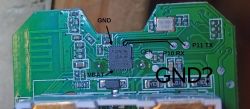
    Suche eine große Masse-Fläche auf der Platine in der Nähe des Chips, z.b. die größere Fläche unter den RX und TX Pins, wo die beiden SMD Teile angeschlossen sind. Messe die Spannung zwischen dem und CEN, die sollte bei etwa 3.3V sein (natürlich kannst du zur Not auch so sicherstellen, ob zwischen dem CEN und dem Netzteil Minus diese Spannung anliegt und deine Versuche legen das ja nahe, dass es passt, wenn der Ping bei Verbindung mit CEN weg ist und später wiederkommt).
    Mit den drei Verbindungen GND, RX und TX sollte es klappen.

    You will need GND, RX and TX, so find a GND pad on the board. Usually a bigger copper area, e.g. the one below RX TX where the two SMD parts are connected.
    Just check voltage between this pad and CEN, should be 3.3V approximately. You might also check against GND of the power supply, just make sure you don't have 19V or so, the chip would die from that voltage!
  • #9 21595997
    blacksun2
    Level 7  
    max4elektroda wrote:
    z.b. die größere Fläche unter den RX und TX Pins, wo die beiden SMD Teile angeschlossen sind.


    welche Stelle meinst du genau? Die Kontakte von den SMD?
    mal blöd gefragt, brauche ich den CEN überhaupt zum Flashen? Tut es bei den Beken-Chips nicht auch ein Neustart, indem ich die Spannung wegnehme und dann wieder anlege?
  • #10 21596041
    max4elektroda
    Level 20  
    Ich hoffe, es wird klar:
    Close-up of a computer motherboard showing an integrated circuit, capacitors, and voltage converters.
    weiß nicht, ob Spannung wegnehmen hier reicht, weil das ja nicht die Spannung am Chip ist, sondern noch Spannungswandler und Kondensatoren dahinter liegen, so dass die Spannung noch etwas länger anliegt, wenn du das Netzteil wegnimmtst
  • ADVERTISEMENT
  • #11 21599325
    blacksun2
    Level 7  
    >>21596041

    nach vielen Versuchen hat es nun geklappt. Jetzt weiß ich, was du gemeint hast. Man muss zusätzlich noch GND vom USB-to-TTL anlegen, zusätzlich zu den Stiften, an denen das 19V-Netzteil hängt.
    Und mit einem weiteren GND vom USB-to-TTL muss man dann kurz den CEN antippen, damit ein Reboot ausgelöst wird.

    Ich habe von dem Chip mit dem Flashing-Tool ein Backup gezogen. Aus diesem Backup konnte das Tool aber keine PIN-Belegung extrahieren. Es hieß:
    "Sorry, no meaningful pins data found. This device may be TuyaMCU or a custom one with no Tuya config data.
    No module information found.
    And the Tuya section starts, as usual, at 2023424"

    Warum ist das so?
    Aus einer anderen smarten Steckdose mit einem BK7231N konnte das Flashtool die PIN-Belegung extrahieren. Da war, glaube ich, der BK7231N auf einer eigenen Platine, die dann senkrecht in die Hauptplatine eingelötet war.
    Wie komme ich nun an die Belegung?

    Hier das Backup-File:


    Vielen Dank.
  • #12 21599423
    divadiow
    Level 34  
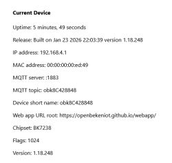
    In the event EF cannot extract config it'll be a case of checking the boot log to see if it's helpfully printed at startup, GPIO doctor trial/error, multimeter tracing or following traces from BK7231N pins on a hi-res image, or trying templates from device list. Or a combination of these things. Here is boot log from your dump

    Code: Text
    Log in, to see the code


    Code: Text
    Log in, to see the code


    which means:

    Code: Text
    Log in, to see the code


    Added after 3 [minutes]:

    divadiow wrote:
    or trying templates from device list

    there are at least 2 other devices in device list with this template. eg https://www.elektroda.com/rtvforum/topic4058389.html
  • #13 21599640
    blacksun2
    Level 7  
    divadiow wrote:
    In the event EF cannot extract config it'll be a case of checking the boot log to see if it's helpfully printed at startup

    Code: Text
    Log in, to see the code


    Wow, I'm really amazed at how you did that.
    Thank you so much for your help.
    How do you record the Tuya boot? How did you get to the log with the Tuya firmware?

Topic summary

The discussion focuses on identifying the flashing pinout for a BK7231N-based SmartPlug purchased from Aliexpress (listing 1005007884300347) originally running Tuya firmware, with the goal to flash OpenBeken. The device's PCB has six unlabeled solder points that do not match the standard BK7231N layout. Analysis of provided images suggests that pins 26 (P10/RX) and 27 (P11/TX) correspond to the two pads below the quartz crystal and should be used for serial communication, connecting chip RX to serial TX and chip TX to serial RX. Powering the device safely for flashing is critical; it is recommended to use a low DC voltage supply (e.g., 12V or 15V) applied to the mains input pins instead of the standard 230V AC to avoid hazards. Polarity is not critical due to the AC design. The CEN (reset) pin is identified as the fourth pin from the top on the right side near two SMD components, which may be used for resetting during flashing. Users report that 12V DC may be insufficient to fully power the device for network operation or serial output, suggesting a higher voltage or direct 3.3V supply might be necessary. Serial log output may be accessible via an unconnected top contact requiring a needle probe. Additional detailed photos of the voltage regulator and power input area are recommended to locate suitable 3.3V and GND points for stable flashing power.
Summary generated by the language model.
ADVERTISEMENT