logo elektroda
logo elektroda
X
logo elektroda

[Solved] Commissioning the ESP8266 01 WIFI module - step-by-step instructions

akr18 3876 21
ADVERTISEMENT
Treść została przetłumaczona polish » english Zobacz oryginalną wersję tematu
  • #1 18132229
    akr18
    Level 11  
    How do I get this module up and running?
  • ADVERTISEMENT
  • #2 18132304
    kaczakat
    Level 34  
    You need to supply 3.3V (to be sure, an output of more than 500mA) and, using the same communication logic, send the appropriate AT commands. A list of AT commands is available by typing the same as in the topic into Google.
    Helpful post? Buy me a coffee.
  • ADVERTISEMENT
  • #3 18132354
    akr18
    Level 11  
    I tried powering it on a contact board from a power supply module of the kind used for contact boards I connected via a voltage converter to rs /USB as in the video of the electroconductor but it does not detect it.
  • #4 18132679
    kaczakat
    Level 34  
    ESP-01 will not be detected by the PC in any way, because it has no USB interface. If you want to run it from a PC, you need a USB-UART converter, connect it to the PC, check what COM port it has been assigned, add drivers if necessary, disconnect it, set it to 3.3V (I recommend the red one with the FTDI chip), connect the TX-RX, RX-TX, GND- GND pins, connect the converter to the PC, supply power to the ESP-01 module, open the terminal with the selected COM port at speed 115200 (other speeds may also work, e.g. 9600, depends on how the ESP is configured at the moment), send an AT command with end-of-line characters and a new line. 9600, it depends how the ESP is currently configured), you send an AT command with end of line and new line characters, if it responds OK, you have established communication and you can send it further commands in this mode.
    I use the ESP with an Arduino, uploading some made up programs or example programs from core ESP to it according to the many tutorials on how to use and program the ESP. For this you also need a UART converter, to upload programs and possibly communicate with the PC. For a start, you may want to look at the sticky topic here: https://www.elektroda.pl/rtvforum/topic3415731.html.
    It is much easier to get started using an ESP board that has such a converter built in, e.g. I recommend the ESP WEMOS mini.
    Helpful post? Buy me a coffee.
  • #5 18132704
    akr18
    Level 11  
    I have connected it through the uart adapter as you write in addition to the 3.3v to 5v converter , at times it reported the version via the terminal to the commands sent at does not respond how to connect the other pins of the module ?
  • #7 18132800
    akr18
    Level 11  
    I have just according to this video done everything , maybe module defective?
  • #8 18132856
    kaczakat
    Level 34  
    If it reports at times and then doesn't then it's more suggestive that something is wrong with your cables.
    All pinology for normal startup:
    VCC to 3.3V
    GND to GND
    RX to TX of 3.3V UART module
    TX to RX of 3.3V UART module
    RST to VCC via R 10k
    CHPD to VCC via R 10k
    GPIO 0 to VCC via R 10k
    GPIO 2 not connected
    If you want to run in flash upload mode, short GPIO 0 to GND and then reset/power up.
    Some modules already have resistors on the board, check the resistance between pins with a meter, if it is 5-12k it means that the above mentioned resistor is unnecessary (i.e. it is already there).
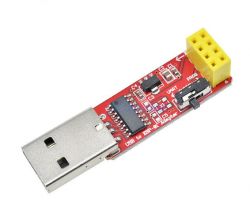
    Just to be sure, buy such an adapter for communication and flash uploading:
    Commissioning the ESP8266 01 WIFI module - step-by-step instructions .
    One switch for each mode, great convenience to start with, no complications with cables connects/disconnects. Unfortunately you have to pull out, switch/connect - they didn't give a button for RST.
    Helpful post? Buy me a coffee.
  • #9 18132874
    khoam
    Level 42  
    akr18 wrote:
    I connected it through uart adapter as you write in addition through voltage converter 3.3v to 5v , at times it reported with version text through terminal on sent commands at does not respond how to connect other pins of module ?
    .
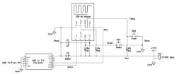
    The wiring diagram of the ESP-01 is as follows:

    Commissioning the ESP8266 01 WIFI module - step-by-step instructions .

    Link: https://www.allaboutcircuits.com/projects/fla...-ESP-01-firmware-to-SDK-v2.0.0-is-easier-now/
  • ADVERTISEMENT
  • #10 18132920
    akr18
    Level 11  
    I will check again , thanks for your replies .
  • #11 18133389
    kaczakat
    Level 34  
    The adapter in the photo above has only CHPD shorted to VCC (no resistor - cheap), the RST on each ESP-01 is pulled up to VCC via 12k (measure your own), and for the flash upload option shorted GPIO 0 to GND via a 2k resistor. So that it is more important to have a good power supply and choose the right speed when sending AT commands.
    You can still do a RESET with a terminal speed of 74k, then it will spit out data right after startup with some information, such as what mode it starts in.
    Helpful post? Buy me a coffee.
  • ADVERTISEMENT
  • #12 18133423
    akr18
    Level 11  
    Today I will do measurements and further tests, when I know something I will write .
  • #13 18134246
    akr18
    Level 11  
    When switched on it prints :
    $€ţ[04]DţťĘ8üťAÄ[18]ń[00]$üü

    NodeMCU 0.9.5 build 20150318 powered by Lua 5.1.4
    lua: cannot open init.lua
    >
    after typing at:
    AT+GMR
    AT+GMR
    stdin:2: '=' expected near 'AT'
    >
  • Helpful post
    #14 18134261
    khoam
    Level 42  
    You have NodeMCU firmware, not AT firmware, so AT commands will not work.
  • #15 18134278
    kaczakat
    Level 34  
    Now the question is what you intend to actually do with it, if you need it for AT commands, then you just do the firmware upgrade described in previous topics in this section.
    If you intend to use it as a uC programmed by the core ESP8266 in the Arduino IDE, then just set it to flash upload mode and load your soft.
    Helpful post? Buy me a coffee.
  • #17 18134328
    khoam
    Level 42  
    Where did you download the AT firmware from?
  • Helpful post
    #19 18134571
    kaczakat
    Level 34  
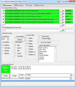
    Descriptions of how to upload the AT flash to the ESP appear here quite often. You download a version of your choice, e.g.
    ESP8266_AT...V1.6.2.zip Download (2.33 MB) .
    You set up the ESP Tool by pointing to the files: Commissioning the ESP8266 01 WIFI module - step-by-step instructions .
    Make sure you have at least 1MB of flash, if it will buffer at QIO (resets after flash upload) then you set slower modes, sometimes I used DOUT.
    Helpful post? Buy me a coffee.
  • #20 18134836
    akr18
    Level 11  
    Probably defective after all , I will purchase a new one , thanks for your help.
  • #21 18136154
    akr18
    Level 11  
    The chip works I have successfully uploaded the batch with the download tool thanks for your help.

Topic summary

To commission the ESP8266 01 (ESP-01) WiFi module, it is essential to supply it with 3.3V and connect it to a USB-UART converter for communication, as the module lacks a USB interface. Proper wiring includes connecting VCC to 3.3V, GND to GND, RX to TX, and TX to RX of the UART module. Additional connections involve RST, CHPD, and GPIO pins, with specific resistors recommended for stable operation. If the module is not responding to AT commands, it may be due to incorrect firmware; users may need to flash the AT firmware if the NodeMCU firmware is present. Troubleshooting steps include checking cable connections and ensuring the correct COM port and baud rate settings. Successful communication is indicated by an "OK" response to AT commands.
Summary generated by the language model.
ADVERTISEMENT