FAQ
TL;DR: To connect a NEO‑6M GPS to a TTGO‑style ESP32, use 9600 bps and “you could use GPIO 13 and 17” by remapping UART pins. This FAQ is for ESP32 TTGO users struggling with RX/TX and power wiring. [Elektroda, khoam, post #18179689]
Why it matters: Correct pin mapping and power prevent dead LEDs and no GPS data.
Quick Facts
- ESP32 UART can be remapped; example: RX=GPIO13, TX=GPIO17 via `SerialGPS.begin(9600, SERIAL_8N1, 13, 17)`. [Elektroda, khoam, post #18179689]
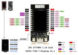
- Some TTGO boards lack GPIO16; hardware Serial pins (1/3, 16/17) may be missing, so remap or use SoftwareSerial. [Elektroda, Anonymous, post #18179647]
- Power the GY‑NEO6M (AliExpress variant) from 5V; its UART logic remains 3V3, safe for ESP32. [Elektroda, khoam, post #18180318]
- TTGO 3V3 rail can be too weak for GPS; symptom: GPS LED never lights. [Elektroda, khoam, post #18180221]
- Cross-connect: ESP RX ← GPS TX, ESP TX → GPS RX, and share GND. [Elektroda, chhriss, post #18179520]
Which ESP32 pins should I connect to the NEO‑6M RX/TX on this TTGO board?
Remap the GPS UART to free GPIOs. Use GPIO13 as ESP32 RX and GPIO17 as ESP32 TX. Wire GPS TX to ESP32 RX and GPS RX to ESP32 TX. Initialize with SerialGPS.begin(9600, SERIAL_8N1, 13, 17). Ensure a common ground between boards. This avoids unavailable hardware UART pins on the TTGO variant. [Elektroda, khoam, post #18179689]
My GPS LED doesn’t light when powered from 3V3—how do I fix it?
The TTGO’s 3V3 output may not supply enough current for the GPS. If the LED stays off, suspect a power shortage before code issues. Use a supply with higher current capability for the module’s VCC. Confirm voltage at the GPS VCC and GND pads while powered. Re-test after addressing power. [Elektroda, khoam, post #18180221]
Can I power the GY‑NEO6M from 5V and still connect its UART to ESP32 safely?
Yes. “Yes, you can power it from 5V. The logic on the UART pins on this module will continue to be 3V3, so you can safely connect to the ESP32.” This provides stable power while keeping logic-level compatibility with the ESP32. [Elektroda, khoam, post #18180318]
What baud rate should I use for NEO‑6M with ESP32?
Use 9600 bps for the GPS serial link. Initialize with SerialGPS.begin(9600, SERIAL_8N1, rxPin, txPin). This matches the working example and typical defaults on these GPS modules. Confirm you see NMEA sentences in your serial monitor after fix. [Elektroda, khoam, post #18179689]
My board lacks GPIO16—can I still use hardware UART?
Yes. ESP32 lets you remap UART pins to other GPIOs. Map RX to GPIO13 and TX to GPIO17, then adjust your Serial.begin line. Avoid assigning pins that are not broken out on your specific TTGO variant. [Elektroda, khoam, post #18179689]
What if my TTGO doesn’t expose UART1 pins 1/3 or 16/17?
Use a remapped UART or SoftwareSerial. Alternatively, use I2C if your NEO‑6M variant supports it. The thread notes the NEO6M0001 offers an I2C option, and your ESP exposes I2C pins already. Verify your module’s capabilities first. [Elektroda, Anonymous, post #18179647]
Where are GPIO13 and GPIO17 on this TTGO board?
Check the corrected pin labels shared in the thread. It shows GPIO16 is not available on this board, but GPIO13 and GPIO17 are. Use those for the remapped GPS UART connections. [Elektroda, khoam, post #18179689]
How do I remap and test the GPS UART quickly?
- Wire GPS TX to ESP32 GPIO13, GPS RX to GPIO17, and GND to GND.
- In code, call
SerialGPS.begin(9600, SERIAL_8N1, 13, 17).
- Open Serial Monitor and confirm NMEA output.
This setup avoids missing hardware UART pins and uses 9600 bps. [Elektroda, khoam, post #18179689]
Could bad soldering cause the GPS not to power up?
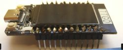
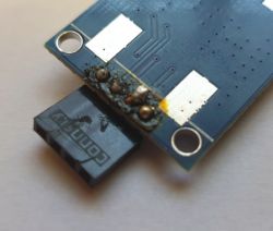
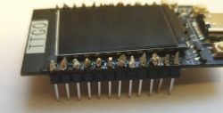
Yes. Poor joints on VCC or GND can prevent power delivery, so the LED never lights. Inspect and reflow dull or cracked joints until they wet the pad and pin. The OP acknowledged imperfect soldering and suspected it was the cause. [Elektroda, chhriss, post #18180371]
What symptoms indicate I mapped to unavailable pins?
You’ll see no GPS data despite correct wiring and code, even though the module powers. Boards lacking GPIO16 will fail if you assign it in Serial.begin. Remap to available pins such as GPIO13 (RX) and GPIO17 (TX). [Elektroda, khoam, post #18179689]
Which exact GPS module was referenced in the thread?
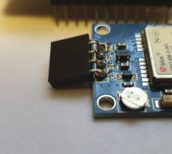
The linked module is a GY‑NEO6M board from AliExpress (NEO‑6M‑0001 style). Use that reference when matching voltage and pinout details during wiring. [Elektroda, chhriss, post #18180285]
How do I upload a sketch to TTGO if auto-upload fails?
Install ESP32 support in Arduino IDE, select your ESP32 board and the correct COM port, and click Upload. If it stalls at “Connecting…”, hold BOOT while starting the upload, then release after it connects. Press EN/RESET once if needed. Install the correct USB-UART driver. [Espressif, 2023]
 .
.
 .
.


