logo elektroda
logo elektroda
X
logo elektroda

Connecting two sensors to the ExtendedIO on the ESP32-2432So35 board - Can it be done? How?

CC_PL 780 16
ADVERTISEMENT
Treść została przetłumaczona polish » english Zobacz oryginalną wersję tematu
  • #1 20506577
    CC_PL
    Level 13  
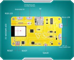
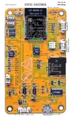
    I have ESP32-2432So35 developer boards (from China), more or less such (from this series):
    Connecting two sensors to the ExtendedIO on the ESP32-2432So35 board - Can it be done? How?

    Connecting two sensors to the ExtendedIO on the ESP32-2432So35 board - Can it be done? How?


    One has inputs for a humidity/temperature sensor, speaker and ExtendedIO as a "general purpose connector".

    The question is whether it is possible, and if so, then how to use this ExtendedIO to connect simultaneously a GPS sensor and an encoder?

    I am browsing the web, there is some information about this board, mainly about its touchscreen display. I have the documentation from their Google Drive page, but nowhere stammered how to use the ExtendedIO 🙂

    Anybody know something, maybe knows this board (or similar) and is able to help?

    The ExtendedIO outputs are 4 pins:

    - GND


    - IO21

    - IO22

    - IO35

    Here are the docs - https://drive.google.com/drive/folders/1S9Joi...1zA?spm=a2g0o.detail.1000023.1.17102169vREj5d

    Directory with 35 at the end in the name. ESP32-2432So35


    Will it be possible to connect at the same time GPS and encoder under this board?


    Thanks in advance for your help!
  • ADVERTISEMENT
  • Helpful post
    #2 20506686
    Zdzicho
    Level 25  
    Encoder - P3 IO21,IO22,IO35
    a GPS - P1 RX
  • ADVERTISEMENT
  • #3 20506712
    CC_PL
    Level 13  
    The GPS is the SAM-M8Q (MATEKSYS). It has 4 pins. And P1 is generally for battery power, the chip is supposed to work "in the field" (so somehow I would have to power via micro USB).
  • ADVERTISEMENT
  • Helpful post
    #4 20506743
    Zdzicho
    Level 25  
    P1, pin 1 of which is the power supply and pins 2 and 3 of which are the RS232 serial communication port with a 3.3V voltage standard, just right for MATEKSYS
    and one more remark, you cannot use the USB communication and RX/TX of the P1 connector at the same time.
  • #5 20506758
    CC_PL
    Level 13  
    The GPS module is this one: http://www.mateksys.com/?portfolio=sam-m8q I'm specifying just to be sure.


    So I just need to take care of the power supply on the microUSB. I'm glad that this will be going soon (I still have to order special plugs for these sockets)...

    Thank you very much for your reply!
    Added after 1 [minute]:
    Zdzicho wrote:
    and one more note, you cannot use USB and RX/TX communication of the P1 connector at the same time

    OK, I understand. This will not be needed. As I wrote above the USB will be used to power the 1S 3.7V Li-Pol battery.
  • #6 20512423
    CC_PL
    Level 13  
    One more question: those white sockets on the board are JST SH1.0-4P ? I wouldn't ask this, but I already bought the cables, they came and .... they turned out to be too small. He wants to make sure now! :) I am asking about the white ExtendedIO and Power Supply sockets.
  • Helpful post
    #7 20512719
    khoam
    Level 42  
    They say 4P-1.25, so they are sockets with a pin spacing of 1.25 mm, not 1 mm. Such plugs are easily purchasable.

    CC_PL wrote:
    These white sockets on the board are JST SH1.0-4P ?
    Definitely, no.
  • #8 20512784
    CC_PL
    Level 13  
    I know they are available to buy, but what are they called? ;) The raster is 1.25mm, 4-pin, but what is their professional name?, as there are dozens of types in the shops and several are quite similar. Probably these are the ones: JST XH 1.25mm 4pin (??)
  • #9 20512820
    khoam
    Level 42  
    You would need to include clear photos of these sockets from the front and top. The documentation you provided links to doesn't say a word about this.
  • ADVERTISEMENT
  • #11 20516488
    CC_PL
    Level 13  
    Thank you Zdzicho

    I bought the JST XH 1.25mm 4pin, it arrived today and is OK - finally!
  • #12 20527034
    CC_PL
    Level 13  
    Zdzicho wrote:
    P1 whose pin 1 is the power supply while pins 2 and 3 are the RS232 serial communication port with 3.3V voltage standard just right for MATEKSYS and one more remark, it is not possible to use simultaneous communication over USB and RX/TX of P1 connector


    I don't know which numbers, pin designations to use in the application for TX and RX. I connected the GPS to the board and it doesn't detect it - error "check wiring".

    I use the TinyGPSPlus library: https://github.com/mikalhart/TinyGPSPlus

    What about simultaneous RX/TX communication in P1 and USB, I understand that I won't be able to view the result on the Monitor (Serial Monitor in Arduino IDE)?

    ---
    Here are the docs: http://pan.jczn1688.com/directlink/1/ESP32%20...d21CmARCmARXj&file=3.5inch_ESP32-3248S035.zip

    Tile auction

    Added after 1 [hour] 16 [minutes]:

    Here's some info: https://dzen.ru/a/ZBs49e6DKmsHHVQk

    I schematy:

    Connecting two sensors to the ExtendedIO on the ESP32-2432So35 board - Can it be done? How?

    Connecting two sensors to the ExtendedIO on the ESP32-2432So35 board - Can it be done? How?

    Connecting two sensors to the ExtendedIO on the ESP32-2432So35 board - Can it be done? How?
  • #13 20527185
    Zdzicho
    Level 25  
    Personally, I would knock out that led1 tricolour and use two of the three ports to communicate with the GPS
  • #14 20527279
    CC_PL
    Level 13  
    Zdzicho, I would not want to interfere so much with the board :)

    In post #4:

    Quote:
    P1 of which pin 1 is the power supply while pins 2 and 3 are the RS232 serial communication port with a 3.3V voltage standard just right for MATEKSYS and one more note, it is not possible to use simultaneously USB communication and RX/TX of P1 connector


    you have recommended P1 connector and I would like to use it
    . Only I don't know what pin numbers are assigned to the outputs in P1.

    U0-RXD - 35 and U0-TXD - 34?? .
  • #15 20527325
    Zdzicho
    Level 25  
    Standard, i.e. RxD - GPIO 03 and TxD - GPIO 01
  • #16 20528169
    khoam
    Level 42  
    Rather, I would use the P3 socket and assign GPIO 21/22 in the program to UART1 for communication with the GPS so as not to block myself with Serial Monitor on UART0.
  • #17 20528178
    CC_PL
    Level 13  
    The socket named ExtendedIO will be used for another sensor. It is already occupied.

Topic summary

The discussion revolves around connecting a GPS sensor (MATEKSYS SAM-M8Q) and an encoder to the ExtendedIO of the ESP32-2432So35 board. The ExtendedIO has four pins: GND, IO21, IO22, and IO35. It is noted that the GPS module requires power from the P1 connector, which is primarily for battery power, and that USB communication cannot be used simultaneously with RX/TX on the P1 connector. The user seeks clarification on the pin designations for TX and RX, with suggestions to use GPIO 21/22 for UART1 communication with the GPS to avoid conflicts with the Serial Monitor. Additionally, there is a discussion about the correct type of connectors for the board, confirming that the ExtendedIO sockets are JST XH 1.25mm 4-pin.
Summary generated by the language model.
ADVERTISEMENT