logo elektroda
logo elektroda
X
logo elektroda

I wanted to make sure I didn't burn the ESP32 (3.3 and 5V logic).

pecet87 1143 3
ADVERTISEMENT
Treść została przetłumaczona polish » english Zobacz oryginalną wersję tematu
  • #1 20548115
    pecet87
    Level 3  
    Hi,

    I wanted to make sure I wouldn't burn the ESP32 by connecting the sensors on 5V (ESP32 logic is on 3.3V)? In my opinion no, only a higher voltage (?) can hurt, but want to make sure. A colleague (somehow) burnt the ESP32 board, so I want to avoid this.

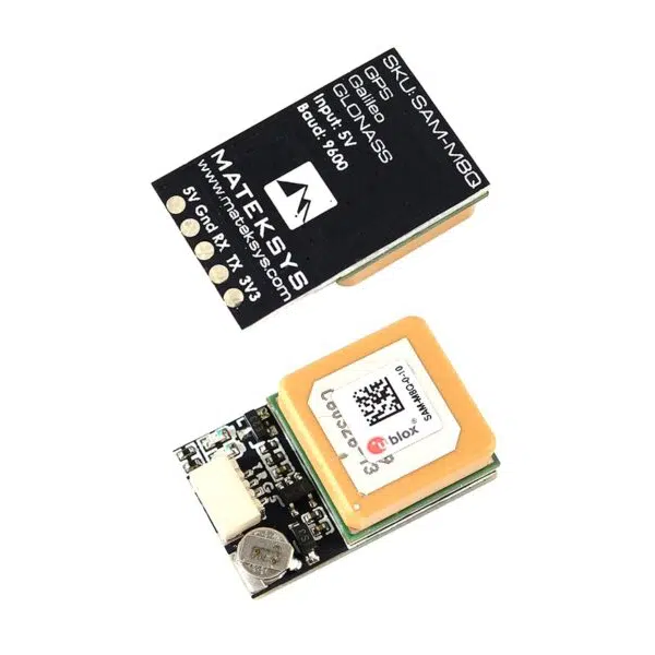
    I have a "rotary encoder", a hygroscopic and temp sensor, a noise level sensor, a SAM-M8Q GPS from ublox and a camera and some other Arduino sensors. In the SAM-M8Q GPS manual, there are two voltages 3.3V and 5V. Apparently the logic goes on 3.3V, but why this information about 5V?

    Is it possible to buy somewhere an extension cable for the camera cable (tape)? This one of mine is not even 5cm.

    I add that I power the ESP32 board from the USB of my laptop.


    Thank you in advance for your help!
    /PC
    Do you have a problem with Arduino? Ask question. Visit our forum Arduino.
  • ADVERTISEMENT
  • Helpful post
    #2 20548160
    kasjo
    Level 26  
    pecet87 wrote:
    In the SAM-M8Q GPS manual there are two voltages 3.3V and 5V. Apparently the logic goes for 3.3V, but why this information about 5V?
    In the catalogue note max Vcc=3.6V. On the schematic of the SAM-M8Q board there is no stabiliser so I don't know where this 5V comes from.
  • ADVERTISEMENT
  • #3 20548218
    pecet87
    Level 3  
    There were both voltages in the module information. But I don't know where these data came from, I didn't understand (I speak English poorly).

    Generally I want to power the sensors by connecting them to the ESP32 boards (without any additional power supply). Of course only the ones that are possible (3.3V).

    Added after 4 [hours] 1 [minutes]:

    There is information on the back of the PCB:

    SKU: SAM-M8Q-0-10
    GPS
    Input: 5V
    Baud: 9600 bps

    There are 5 leads at the 4 pin connection (ie. 5 fields are soldered on the board) respectively:

    5V, Gnd, RX, TX and 3V3.

    A little strange this information about 5V?

    I wanted to make sure I didn't burn the ESP32 (3.3 and 5V logic).
    I wanted to make sure I didn't burn the ESP32 (3.3 and 5V logic).

    Added after 3 [hours] 35 [minutes]:

    According to,. specs:

    https://content.u-blox.com/sites/default/files/SAM-M8Q_ProductSummary_%28UBX-15027452%29.pdf

    Supply voltage 2.7 V to 3.6 V
    Digital I/O voltage level 2.7 V to 3.6 V
    Power Consumption (2 concurrent GNSS) 29 mA @ 3.0 V (Continuous) 9.5 mA @ 3.0 V
    Power Save mode (1 Hz)
    Backup Supply 1.4 V to 3.6 V

    The only thing that bothers me is this 5V on the PCB on the back and in the attached post above pictures. In the documentation they mainly write about 3v3 but sometimes 5V scrolls through.
  • #4 20548789
    TvWidget
    Level 38  
    There is probably a stabiliser on the board to get 3.3V from 5V.
ADVERTISEMENT