logo elektroda
logo elektroda
X
logo elektroda

6 KWp photovoltaic installation - diagram and connection method

trzepak 280992 131
ADVERTISEMENT
Treść została przetłumaczona polish » english Zobacz oryginalną wersję tematu
  • #31 18489465
    TAGBA
    Level 11  
    The person who signs for the installation, in addition to sep E and D, must also have measurements. But what is needed, including the installer's requirements, is written in the application that must be submitted.

    Only this application is submitted as a prosumer up to 50kW in Energa Link plus of course all the documents mentioned in this application.

    I sent everything by e-mail.
  • ADVERTISEMENT
  • #32 18489645
    Z1mmy
    Level 8  
    Ok, thank you for the answer, but also an auxiliary question.
    I know the Energi website and read all the steps including reporting the installation.
    Since it is only this diagram, similar to how a colleague attached a few posts above (thanks again!), This is the question. On it there is a section for signatures developed and installed.
    I understand that the study can only be sealed by someone who has a permit or building qualifications?

    Does SEP alone authorize you to draw?

    And additional questions.
    1 I read in the fire regulations that above 6.5kw, installations should be reported to the firefighter. Someone practiced it?
    2 how are the Rapid Shutdown Device standards for oze installations in Poland? It is about in case of fire, cutting off electricity at the panels remotely. So that no electricity flows inside the building. I read somewhere about a cubature that exceeds 1000 m3. But this may apply to the installation in general and not to the installation itself?

    Thanks
  • ADVERTISEMENT
  • #33 18490720
    TAGBA
    Level 11  
    Sep is enough to draw a schematic. They are interested in security, so that you do not disturb their networks sometimes.

    1. Not practiced and I have 10kW
    2. There are no requirements. But when a lot of roofs start burning, they will probably move in.
  • #34 18491309
    Z1mmy
    Level 8  
    It's not about burning roofs.
    If they are to burn, they will burn. You won't turn off the installation anyway. You will only cut off the wires that go to the building. It is about the safety of firefighters during operations and saving people.
    This is why there are reports to the guard above 6.5kw because there are potentially high voltages and currents and they need to know how to extinguish such a building. They should keep at least 5m from the wires, etc., and the roof should be powder-extinguished.
    So when it burns it will, RSD will not stop it, but it will ensure (greater) safety during the firefighting operation.
  • #35 18492127
    TAGBA
    Level 11  
    Do you think that when firefighters see the panels on the roof, they do not have a special procedure for extinguishing such installations so as not to endanger their lives? Even if you don't report it. Tell me why, then installations from 6.5kW should be reported to the guard. After all, in an installation of 2 or even 1kW, current may flow above the assumed safe limit for direct current, i.e. 50V.
  • #36 18494480
    Z1mmy
    Level 8  
    I don't know, someone made such assumptions. However, I saw such records and wondered if anyone respects it :)
  • #37 18518810
    vulture30
    Level 11  
    TAGBA wrote:
    I reply to PW " Hi,
    I wanted to ask you about this diagram that you showed for the energy of PV installations.
    Did they accept him and make decisions about joining? Did you have to change something? Is this form ok?
    And an additional question, how did you draw this schema? Any convenient tool?

    Thanks
    Paul
    "

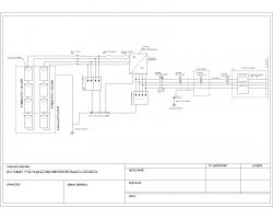
    I am attaching the current diagram, which I have submitted to Energa Operator and which has been approved and issued the permit.
    Drawn in AutoCad.
    Important note. It is best to call energy or look at the contract and the data of the object on the application as well as in the drawing should be identical to the contract. Even if it is not covered with reality.

    6 KWp photovoltaic installation - diagram and connection method

    I additionally attach a file in the .dwg version

    Thanks for the diagram.
    I have questions, maybe someone could comment.

    1. Should there be no surge arresters on the DC side in front of the fuse switch disconnector (on the panel side) so that there is protection even when the switch is turned off?

    2. Why two disconnectors on the DC side?

    3. PE in the main switchboard to what is it connected? To N?

    4. Do you have a TN-C network? 4x35mm2 comes out of WLZ. 3xL + N? And not PEN?
    Then he goes to RG and PE shows up. N itself flies to the inverter and there the PE of the inverter is connected to a separate ground.
    So, the inverter works in the TT grid. ABB can work in TT?
    Do I generally misinterpret something? :)
  • #38 18520207
    Z1mmy
    Level 8  
    briefly answering:
    I am attaching a sample image for the installation that I make for the client.
    1 YES, the protectors should be in front of, what sense they have for, as lightning is the main thing, the disconnector will cut off the flow and will not go to the protector.
    2 It makes no sense 2. Unless there are several parallel strings, then they should be used to cut off the reverse currents in the event of a short circuit on the panel if it breaks.

    As a rule, the arresters and all PE should be connected to the main equalization rail and this one to the property's efficient earth electrode. If this does not exist, it should be made and measured. There are no regulations on resistance for the earth electrode, but the adopted rules are
  • ADVERTISEMENT
  • #39 18520623
    vulture30
    Level 11  
    Thanks for the quick and specific answer.

    There is no attachment you wrote about.
  • #41 18521118
    TIGIS
    Level 16  
    Are you doing one string for almost 10kWp? Is the max voltage not exceeded in NOCT? Because the switch on the DC side is 20A and the panels are over 10A, which suggests 1 string.
  • #42 18521183
    Z1mmy
    Level 8  
    Please have a look at the legend.
    Solar Edge Power Optimizers.
    The maximum string length is 50 panels or 11250 W per string.
  • #43 18521436
    3301
    Level 34  
    Z1mmy wrote:
    I didn't attach it, sorry.


    What happens to the protective conductor of the YDY 5x4 cable inserted into the RAC?
  • #44 18521595
    Z1mmy
    Level 8  
    Ok, she didn't draw :D
    As a rule, I am not interested in the existing part :) The diagram shows the connection of the PV installation. But yes, I will correct it of course. The project itself is only a draft because I haven't been to the client yet. What I will find out will turn out.

    Thanks for your vigilance! :)
  • #45 18573877
    TAGBA
    Level 11  
    2. Why two disconnectors on the DC side?
    Two are for the fact that one is factory-mounted in the Inverter and if it is necessary to return the inverter for warranty, I have nowhere to disconnect.
  • #46 18578118
    Z1mmy
    Level 8  
    Besides, not every inverter has built-in safeguards. For example, Solar Edge has, but from larger sizes. It all depends on the case. And yes, I prefer to give two of the reasons I wrote.
  • #47 18578277
    Janusz_kk
    Level 39  
    Z1mmy wrote:
    1 YES, the protectors should be in front of, what sense they have for, as lightning is the main thing, the disconnector will cut off the flow and will not go to the protector.

    But when the protector falls, you will replace it under voltage or at night :)
    two, the lightning pulse is probably too short to blow the fuse, so the circuit breaker behind the disconnection fuse still protects.
  • #48 18578414
    noja102
    Level 24  
    As a lightning bolt, your protections together with the inverter will evaporate from half of the installation.
  • #49 18578436
    Z1mmy
    Level 8  
    Janusz_kk wrote:
    Z1mmy wrote:
    1 YES, the protectors should be in front of, what sense they have for, as lightning is the main thing, the disconnector will cut off the flow and will not go to the protector.

    But when the protector falls, you will replace it under voltage or at night :)
    two, the lightning pulse is probably too short to blow the fuse, so the circuit breaker behind the disconnection fuse still protects.


    Not. Because Solar Edge, as in the diagram we are talking about, is based on power optimizers that have safe DC functions. Which means that when you turn off the inverter, you have 1V for each panel up to a maximum of 50 panels in a string, i.e. 50V DC. You can disconnect and replace the protector, fuses etc. in full sun.
    In a kalsic installation, yes. You have to either cover the panels or do it when there is no sun.
  • #50 18581084
    TAGBA
    Level 11  
    Z1mmy wrote:

    Not. Because Solar Edge, as in the diagram we are talking about, is based on power optimizers that have safe DC functions. Which means that when you turn off the inverter, you have 1V for each panel up to a maximum of 50 panels in a string, i.e. 50V DC. You can disconnect and replace the protector, fuses etc. in full sun.
    In a kalsic installation, yes. You have to either cover the panels or do it when there is no sun.


    Anyone know how such optimizers work? What's happening with the tension? The inverter lets go of the protective ground?
  • #51 18581511
    Janusz_kk
    Level 39  
    TAGBA wrote:
    What's happening with the tension? The inverter lets go of the protective ground?

    Nothing happens, disconnects the panel from the optimizer. The optimizer is a converter but quite specific, it must pass the current through itself in series, and when the panel gives something, it adds voltage to this series, and + control which is on DC.
  • ADVERTISEMENT
  • #52 18583660
    Misiorrr
    Level 8  
    I'm joining the discussion because I have a problem with the scheme for connecting the micro-installations to the tauron network.
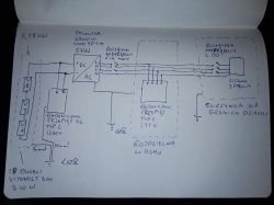
    18 panels of 310W Vitovolt in one chain
    Froniu symo 5.0 inverter 3 m
    installation installed, checked. everything works. I reported a week ago on Wednesday. I sent the installation connection diagram, all documents, form, etc.
    today I got an email from tauron


    we have received your application for connecting the micro-installations to the network, unfortunately it is incomplete / incorrectly completed.
    What is missing from the application
    Please complete your application with the following documents / information:
    a) a diagram of the facility's electrical installation showing how to connect the micro-installations


    I did the installations myself. I also made the diagram myself by hand with a ballpoint pen on a piece of paper.

    6 KWp photovoltaic installation - diagram and connection method

    I called the helpline but the ladies there can only read the rules. there is no option to speak to an engineer who can tell me what is wrong.
    I note that I have SEP G1 E and D qualifications
  • #53 18583824
    Tech132
    Level 28  
    There is no stamp and electrician's signature on the diagram.
  • #54 18583853
    Misiorrr
    Level 8  
    if I do not have a stamp because I do not have a business, the signature is enough? I wanted to add that I also sent them photos of the permissions
  • #55 18583871
    tom.pk
    Level 16  
    I think the schema should contain the object data - ADDRESS
    I wrote;
    SCHEME OF ELECTRICAL INSTALLATION OF THE FACILITY WITH CONNECTION
    PHOTOVOLTAIC MICRO INSTALLATION WITH POWER ...... Name, surname ....... address .....
  • #56 18583877
    Misiorrr
    Level 8  
    OK thanks. so if I sign and write the address, it will be enough? will they accept without a stamp?
  • #57 18583884
    tom.pk
    Level 16  
    Misiorrr wrote:
    OK thanks. so if I sign and write the address, it will be enough? will they accept without a stamp?

    I do not know, the scheme itself was similar, if you gave the permissions, a stamp is unlikely to be needed by many people
    mounts having permission without running a business and passes.
  • #58 18595739
    comer3
    Level 27  
    Hello,

    I look at the diagrams posted here for connecting surge arresters and I see that the connections are different. I wonder if, for example, when making a PV installation on a farm building and this installation will have its own grounding of the supporting structure / panel frames + the DC surge arresters will be connected to this ground, should the AC side, and specifically the PE core, also be connected to this ground? If not, how to correctly install the surge arrester (T1 + T2) in the switchgear next to the inverter? The cable between the inverter and the RG will be 40m (5x4mm2) - there is no place in the RG to install this protector, and it is currently not physically possible to connect these two different earth electrodes (RG and PV) with a bender. It seems to me that connecting the PE conductor to this PV grounding in the event of a discharge (I'm not talking about a direct one) will definitely shorten the surge / induced current path to the ground, but I do not know if it is correct when it comes to the operation of the inverter (it will be Fronius, and from what I have read it, it cannot work in the TT network).

    My friend Misiorrr let me know if Tauron only meant the stamp and address on the diagram as soon as you get an answer from them :D
  • #59 18596048
    AT PRO
    Level 23  
    comer3 wrote:
    Hello,

    (it will be Fronius, and from what I read it cannot work in the TT network).

    :D


    According to the manufacturer, it cannot, but on the frontier forum, to the question why they cannot work in TT, no one has not sensibly answered yet.
  • #60 18653582
    wello
    Level 20  
    Z1mmy wrote:
    You have to either cover the panels or do it when there is no sun.

    Or make an SPD box with MC4 sockets. Then, after turning off the inverter, it is enough to disconnect the MC4 plugs going from the panels, from the MC4 sockets in the box.

Topic summary

The discussion revolves around the installation of a 6 kWp photovoltaic system, specifically addressing the connection methods and necessary protections for compliance with local regulations. The user has purchased a kit consisting of 22 Just Solar 285W panels and a Growatt 3-phase 6000W inverter. Key points include the need for overcurrent protection on both the DC and AC sides, the inclusion of a surge arrester, and the requirement for a ZE energy meter in the installation diagram. Participants emphasize the importance of proper grounding and equipotentialization between the photovoltaic system and the existing electrical installation. There are also discussions about the documentation required for connecting to the grid, including the necessity of a signed diagram and the potential need for building qualifications. The conversation highlights various technical aspects, including the use of fuses, the configuration of strings, and the implications of regulations for self-installers.
Summary generated by the language model.
ADVERTISEMENT