logo elektroda
logo elektroda
X
logo elektroda

6 KWp photovoltaic installation - diagram and connection method

trzepak 281007 131
ADVERTISEMENT
Treść została przetłumaczona polish » english Zobacz oryginalną wersję tematu
  • #91 19009807
    04.21
    Level 9  
    Hello

    Recently, when I wrote it down, I had these parameters entered, it was just in the SMA inverter
    but also look for the declaration of settings of this inverter in Polish
  • ADVERTISEMENT
  • ADVERTISEMENT
  • #93 19011273
    luki2099
    Level 10  
    Thank you for the inverter settings.

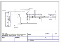
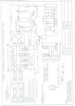
    I have another question, could you please take a look at the diagram below? will such a drawing pass in Energa?

    3-phase installation, contracted power 11kW, pre-meter protection 25A

    6 KWp photovoltaic installation - diagram and connection method


    best regards
  • #94 19012141
    04.21
    Level 9  
    Hello

    There may be such a diagram, but it is not necessary to draw the installation so accurately you draw one line, you mark that it is a 3F connection and that's enough.
    I look at it still and see that the protection on the DC side has 15A, I think it's a bit too high, see what the short-circuit current for these panels is definitely not 15A.
    In fact, with one string, there is no need to use such protection, the fewer connections the better and one more security issue on the AC side, I see that you have C40 and C60 written, I don't think you have such.
    One more thing I do not know if you will be expanding this installation, but in this situation the power of the inverter is too high
    on the DC side, the circuit should always be oversized at least 20% in our conditions, I prefer approx
    25-30%

    Added after 36 [minutes]:

    The table with the yields for different power of inverters is just for the fronius
    all these inverters worked with the same number of panels.
    Of course, not all inverters can be oversized as much as Sofar 5.5 is the recommended power of 7320W
    for this number of panels it was easy to install Sofar 4.4 KW and the most optimal 3.7 KW but this company just does not have such power.
    The last thing is also the power drop over time
    this is the calculation for a south-facing installation with a slope of 37 degrees

    Inverter Modules configuration SM inverter power Annual production Loss vs Optimum Yield kWh / kWp
    Fronius SYMO 8.2-3-M 20 pcs for MPPT1 + 2 8.2 kW 72% 6184.67 kWh -0.6% 1030.78
    Fronius SYMO 7.0-3-M 20 pcs. For MPPT1 + 2 7.0 kW 84% 6203.74 kWh -0.3% 1030.96
    Fronius SYMO 6.0-3-M 20 pcs. For MPPT1 + 2 6.0 kW 98% 6220.21 kWh max. 1036.70
    Fronius SYMO 5.0-3-M 20 pcs for MPPT1 + 2 5.0 kW 118% 6187.04 kWh -0.5% 1031.17
    Fronius SYMO 4.5-3-M 20 pcs for MPPT1 + 2 4.5 kW 131% 6111.31 kWh -1.8% 1018.55
    Fronius SYMO 3.7-3-M 20 pcs for MPPT1 + 2 3.7 kW 159% 5834.51 kWh -6.2% 972.42
    Fronius SYMO 3.0-3-M 20 pcs for MPPT1 + 2 3.0 kW 196% 5405.12 kWh -13.1% 900.85
  • ADVERTISEMENT
  • #95 19012554
    luki2099
    Level 10  
    Thanks for the advice,

    The inverter is in stock, as panels will be added (probably next year).
    The fact disconnectors I have not had to be changed. I will also reduce the protection on the DC side to 12A

    In general, we agreed with the electrician today that the meter will nevertheless be in the switchboard outside the building.
    The diagram will be drawn again, on Monday I will post the correct one - if someone wants to look,

    best regards
    Luke
  • #96 19016135
    emartinelli
    Level 1  
    Hello everyone.
    I have a question about schematics. From what I can see, there are two versions looking at the AC side from the inverter side (simplified):
    1. Inverter - overcurrent protection - overvoltage limiter - for the existing installation
    2. Inverter - overvoltage limiter - overcurrent protection - for the existing installation
    In my opinion, the second option is probably more correct, although I am not sure myself. Hence the question what is the correct security order and is the difference really necessary?
  • #97 19017683
    04.21
    Level 9  
    Hello
    Normally, in the house, we install a surge arrester behind the main protection of the house or apartment.
    then the rest.
    Theoretically, this is what protects us with discharges from the power grid.
    Now we can ask ourselves if we want to protect ourselves from the inverter side
    basically there is no such need because inverters have such protections in them
    and after the above 275V, the varistor may be damaged, often as we have floating zero.
    One more thing for such protection to work well must be a good earth electrode with low resistance.
    The last thing, if there is a direct discharge, it basically won't help.

    best regards
  • ADVERTISEMENT
  • #98 19067479
    snycesz
    Level 9  
    Good day.
    I do not want to start a new topic, so I will ask a question here. A sales representative of a company was at my place and offered a PV installation. What surprised me, (if the nomenclature is wrong, sorry) the lightning protection / additional grounding of the panels is done additionally. And from what you explained, they drag yellow-green 16mm2 from the panels to the DC switchboard with DC cables and spread to other elements of the system.
    Friends have, for example, a separate cable to the ground and stuck pins? How is it legally regulated?
    Thank you and best regards.
  • #99 19067493
    Merio186
    Level 17  
    snycesz wrote:
    Good day.
    I do not want to start a new topic, so I will ask a question here. A sales representative of a company was at my place and offered a PV installation. What surprised me, (if the nomenclature is wrong, sorry) the lightning protection / additional grounding of the panels is done additionally. And from what you explained, they drag yellow-green 16mm2 from the panels to the DC switchboard with DC cables and spread to other elements of the system.
    Friends have, for example, a separate cable to the ground and stuck pins? How is it legally regulated?
    Thank you and best regards.

    Perhaps I will stick a stick into an anthill, but I think that when making a PV installation, the earth electrode in the building should be verified. If it is not there, it should be done. And here the real fairy tale begins, because making a real earth electrode costs both material and work. And it is good to inform the customer that the price of the earth electrode will be additional because it is impossible to measure how many pins or hoops will go to the earth electrode.

    It makes no sense to dwell on the earth cross-section or preliminary measurements to determine the resistivity and predict the amount of material. During the valuation, there is no electrician in the warehouse, and the cross-section of the land is so diverse that either the valuation is made with a large margin or the truth is told - payable additionally.

    But if the customer does not agree, how to put into use an endless installation?

    The answer to the specific question and the rope. If you have a lightning rod on the roof and the separation distances are kept, then pulling the line to the GSW is correct in my opinion. If you do not have separation distances, it is a mistake to enter the house with the ground wire.
  • #100 19068563
    snycesz
    Level 9  
    Thanks for the quick reply. I will add this curiosity because I forgot about it in the morning. the gentleman suggested that it was similar to the cable from the AC switchboard to the power socket in the garage. Because I have the main switchgear in another part of the house where access is HUGE difficult.
  • #101 19069062
    Merio186
    Level 17  
    snycesz wrote:
    Thanks for the quick reply. I will add this curiosity because I forgot about it in the morning. the gentleman suggested that it was similar to the cable from the AC switchboard to the power socket in the garage. Because I have the main switchgear in another part of the house where access is HUGE difficult.
    This is normal practice. You just have to be very careful and pay special attention to the cross-section of the cable to the socket. Often, power sockets are connected with a 2.5 mm cable or even with a four-wire installation. Simplifying a lot, 6kW to 2.5mm2 is theoretically ok, but the question of line length and voltage drop remains. You have to analyze and just plug in ;)
  • #102 19070543
    04.21
    Level 9  
    Merio186 wrote:
    snycesz wrote:
    Good day.
    I do not want to start a new topic, so I will ask a question here. A sales representative of a company was at my place and offered a PV installation. What surprised me, (if the nomenclature is wrong, sorry) the lightning protection / additional grounding of the panels is done additionally. And from what you explained, they drag yellow-green 16mm2 from the panels to the DC switchboard with DC cables and spread to other elements of the system.
    Friends have, for example, a separate cable to the ground and stuck pins? How is it legally regulated?
    Thank you and best regards.

    Perhaps I will stick a stick into an anthill, but I think that when making a PV installation, the earth electrode in the building should be verified. If it is not there, it should be done. And here the real fairy tale begins, because making a real earth electrode costs both material and work. And it is good to inform the customer that the price of the earth electrode will be additional because it is impossible to measure how many pins or hoops will go to the earth electrode.

    It makes no sense to dwell on the earth cross-section or preliminary measurements to determine the resistivity and predict the amount of material. During the valuation, there is no electrician in the warehouse, and the cross-section of the land is so diverse that either the valuation is made with a large margin or the truth is told - payable additionally.

    But if the customer does not agree, how to put into use an endless installation?

    The answer to the specific question and the rope. If you have a lightning rod on the roof and the separation distances are kept, then pulling the line to the GSW is correct in my opinion. If you do not have separation distances, it is a mistake to enter the house with the ground wire.


    Hello
    I also agree with this entry 100%.
    If the customer does not agree, I, for example, give up such an installation.
    You can even connect the structure with a 6mm cable, but this only meets the requirements of potential equalization.
    I found such a case, the lightning protection system on the building kept the distance, and the lightning discharge went to the structure and there were problems.
    Therefore, as already assumed such an installation, the cost of a good earth electrode must be included in it when I make the installation whether there is a lightning protection system or not, I always make an external earth electrode and that's it.

    The second issue is connecting the inverter to the home installation.
    There have been three fires in single-family houses with PV installations in my area recently, many people have asked me if they are so emergency.
    We have new regulations in this topic, I will not write about them because my hands are falling.
    The cause of these fires, this is an interesting case, was not the DC side but the AC side and behind the inverter too small cross-section of the cable
    and connection in the home switchboard common switching on with a 3 cable for security, you know there is no place, etc.
    This is done for many years and if there is no place, then you need to find them, the power distribution should be done, and no additional cables are screwed in.
    It is worth paying attention to this because then there is no place now, because there is no home.
  • #103 19137336
    studniarz
    Level 20  
    04.21 wrote:
    There have been three fires in single-family houses with PV installations in my area recently, many people have asked me if they are so emergency.

    My friend.
    Please provide more detailed information on these fires. Cities and dates.
    I would love to verify the truthfulness of your "news" and my colleagues from the forum would also learn the causes of these fires. On another forum I took up the topic of another friend who spread similar stories and after verifying the events presented by him, it turned out that the burning houses presented in his story - (7 fires) from this one fire, there was no PV installation in the other house, and the others had PV this way, but in each of these fires the reasons were different than the PV installation, in one of the events there was a fire in the switchgear with the PV installation plugged in, but the short circuit was made by ..... phase controls, which should have separate protections.
    Best regards.
  • #104 19204330
    An-2
    Level 12  
    Z1mmy wrote:
    briefly answering:
    I am attaching a sample image for the installation that I make for the client.
    1 YES, the protectors should be in front of, what sense they have for, as lightning is the main thing, the disconnector will cut off the flow and will not go to the protector.
    2 It makes no sense 2. Unless there are several parallel strings, then they should be used to cut off the reverse currents in the event of a short circuit on the panel if it breaks.

    As a rule, the arresters and all PE should be connected to the main equalization rail and this one to the property's efficient earth electrode. If this does not exist, it should be made and measured. There are no regulations on resistance for the earth electrode, but the adopted rules are
  • #106 19403709
    wello
    Level 20  
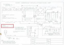
    The scheme itself should go through. Just add a table with the name of what it concerns, address, name and surname of the designer, permission number, date and that's it.
  • #107 19463403
    mk_syst
    Level 1  
    kosmos99 wrote:
    No protection on DC side.
    PGE also requires a D.

    What kind of security?
  • #108 19518839
    ttborys
    Level 2  
    Hello, is there anyone on the forum who can do a pv micro installation diagram for pge ... of course for a fee :)
  • #109 19518857
    noja102
    Level 24  
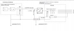
    And please, please 6 KWp photovoltaic installation - diagram and connection method send beer to email
  • #110 19518899
    ttborys
    Level 2  
    Thank you, friend, maybe you have something like this with two strings in a bit better quality because what you sent is very poorly read

    Added after 5 [minutes]:

    and I forgot the double RPV-DC due to the distance above 10 m
  • #112 19519037
    ttborys
    Level 2  
    Ooooo buddy, this is respected, thank you very much

    Added after 50 [seconds]:

    Ooooo buddy, this is respected, thank you very much
  • #113 19519129
    tyqva
    Level 35  
    But how do I get the "Earth Resistivity" lower than 10Ohms? 6 KWp photovoltaic installation - diagram and connection method
    In most earth electrode locations, the soil would have to be replaced with one with good resistivity....
  • #114 19575736
    on6222
    Level 11  
    Hello, and how to describe the complete Growatt wirebox protection in such a diagram, because I am looking for the diagrams as it is drawn but I can not find it


    regards
  • #115 19627899
    janus_z
    Level 12  
    In which program, apart from AutoCAD, do you draw diagrams? do you have any pattern, e.g. in Word?
  • #117 19628055
    janus_z
    Level 12  
    And someone knows a program that will do a simple edition of the AutoCAD file, because I found a diagram in this format, but I do not have AutoCAD itself.
    I ask uncle google but so far I have found nothing.
    ps. this KiCad has i can see its format and the * .dwg file will not open
  • #118 19628404
    wello
    Level 20  
    janus_z wrote:
    In which program, apart from AutoCAD, do you draw diagrams? do you have any pattern, e.g. in Word?

    I was drawing in MS Paint. You really don't need anything else for a single-line diagram.
  • #119 19661330
    paweldre
    Level 9  
    Hello,

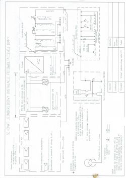
    I have such a scheme, will it pass in Tauron?
    6 KWp photovoltaic installation - diagram and connection method
  • #120 19681615
    kubelos
    Level 1  
    Hello all

    Request for information:
    1. If it is necessary to extend the cables from the PV string, can they simply be soldered and insulated?
    2. I currently have 1 string of 6 panels with a capacity of 370Wp each connected in series. Roof angle 35stp, east side. Measuring on the main switch before the inverter, the whole circuit gives 240V and 1.8A with "good" sun, no shading. Are these parameters correct?

    Thank you for your answer

Topic summary

The discussion revolves around the installation of a 6 kWp photovoltaic system, specifically addressing the connection methods and necessary protections for compliance with local regulations. The user has purchased a kit consisting of 22 Just Solar 285W panels and a Growatt 3-phase 6000W inverter. Key points include the need for overcurrent protection on both the DC and AC sides, the inclusion of a surge arrester, and the requirement for a ZE energy meter in the installation diagram. Participants emphasize the importance of proper grounding and equipotentialization between the photovoltaic system and the existing electrical installation. There are also discussions about the documentation required for connecting to the grid, including the necessity of a signed diagram and the potential need for building qualifications. The conversation highlights various technical aspects, including the use of fuses, the configuration of strings, and the implications of regulations for self-installers.
Summary generated by the language model.
ADVERTISEMENT