logo elektroda
logo elektroda
X
logo elektroda

6 KWp photovoltaic installation - diagram and connection method

trzepak 281001 131
ADVERTISEMENT
Treść została przetłumaczona polish » english Zobacz oryginalną wersję tematu
  • #61 18664342
    Misiorrr
    Level 8  
    comer3 wrote:
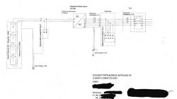
    Buddy Misiorrr, let me know if Tauron only meant the stamp and address on the diagram as soon as you get an answer from them

    I made a more aesthetic version and I gave the address, signature and authorization number
    6 KWp photovoltaic installation - diagram and connection method
    I called the Tauron hotline because no e-mail came and I got the info that everything is ok and the meter is to be installed by May 14. It exceeds the 30 days referred to in the installation notification, but during the corona I am understanding
  • ADVERTISEMENT
  • #62 18673107
    wello
    Level 20  
    Out of curiosity, when did you post the updated schematic? Because according to the regulations, they have 30 days after their approval of documents, and in the case of updates, after approval of the updated ones.
  • #63 18675616
    Misiorrr
    Level 8  
    Yesterday the counter was mounted. I sent the corrected diagram on April 5th. According to the data provided by the fitter, the notification was processed on 01.04, so they had until 14.05. Everything on time. Only when you wait for it, looking at the weather, it hurts a bit. I have already configured the datamenager and start observations.
  • #64 18675757
    wello
    Level 20  
    Do you have a meter outside or at home? I am curious if they have already resumed the assembly inside, because the information about the suspension was on Facebook, but there was silence about the resumption.
  • #65 18677659
    Misiorrr
    Level 8  
    The fitter told me that if the client agrees to enter the house, he is ready to be assembled at home and assembled.
  • #66 18678257
    vulture30
    Level 11  
    Misiorrr wrote:
    comer3 wrote:
    Buddy Misiorrr, let me know if Tauron only meant the stamp and address on the diagram as soon as you get an answer from them

    I made a more aesthetic version and I gave the address, signature and authorization number
    6 KWp photovoltaic installation - diagram and connection method
    I called the Tauron hotline because no e-mail came and I got the info that everything is ok and the meter is to be installed by May 14. It exceeds the 30 days referred to in the installation notification, but during the corona I am understanding


    How are you grounding done? Could you explain?
    One is old from the home installation where the AC SPD is connected and the other is the new grounding from the PV where the construction and DC SPD are connected? I interpret well?

    Are both earth electrodes connected to each other (they are not in the picture)?
    Where did you connect the inverter grounding screw?
    The PE conductor between the inverter and the AC SPD is not connected to the PEN? Do you have TN-C at all or what?
  • #67 18678713
    Misiorrr
    Level 8  
    I did additional grounding (3 pins connected by a hoop) I got 8.35ohm. I connected constructions and panels as well as SPD DC to it. the inverter and everything on the AC side is connected to the terminal block in the main switchboard. grounds are not connected. I have an AC SPD in the main box and an overcurrent switch at the inverter on the AC side
  • ADVERTISEMENT
  • #68 18683418
    comer3
    Level 27  
    Hello,

    As far as I know, inverters (and certainly Fronius) measure the insulation resistance between the positive and negative poles of the PV module chain and the ground at startup. For Fronius, the insulation value must be higher than 1.1MOhm so that the inverter can safely start (for the user). In the case of such separated earthing, the inverter will never detect a failure of the strings (leakage / puncture of the module to the frame, frayed wires, etc.) and will start the installation despite the failure that threatens the user's life. It seems to me that the grounding of the inverter should be connected to the ground of the DC side so that the inverter can correctly interpret its measurements and, depending on their results, react appropriately.

    Just out of curiosity, I will ask my friend Misiorrr what kind of inverter documents did you submit to Tauron? Is it enough to submit the declaration of compliance with the NC RFG network codes taken from the last link in this article https://www.forum-fronius.pl/zgodnosc-nc-rfg/ and is it enough, is it necessary to print something else (e.g. EN certificate -50549-1 or similar)?
  • #69 18683685
    vulture30
    Level 11  
    Comer3, it depends on the resistance between the earth electrodes. If low it should detect.
    Someone checked whether the inverter's PE terminal is short-circuited with the grounding screw on its housing?
  • #70 18683889
    noja102
    Level 24  
    comer3 on the ZE form you have written what they require, these are panel and inverter data sheets and NC RfG declaration. And as for grounding, you are right, the inverter is to be connected to the same grounding strip as the SPD from the DC side
  • ADVERTISEMENT
  • #71 18686300
    comer3
    Level 27  
    Yes, it is generally written on the application, but I would prefer to have confirmation from people who have already submitted their papers to Tauron and had a positive application, what exactly - as far as the inverter is concerned - is required. All you need is the data sheet of the inverter + NC RfG certificate, or do you also need to submit a translation of the declaration of conformity EN_50549-1 and EN_50438 available on the Fronius forum?
  • #72 18686348
    3301
    Level 34  
    data sheet of the inverter + NC RfG certificate, declaration of conformity EN_50549-1 and EN_50438 in Polish
  • #73 18687836
    wello
    Level 20  
    Just today I got a message from Tauron, incl. with the information about it, which reads: "At the same time, we pay attention to submit only the documents listed as attachments to the notification with the notification of micro-installations." And the listed attachments are:
    1. Scheme of the electrical installation of the facility showing how to connect the micro installation.
    2. Technical parameters, operational and operational characteristics of connected devices, installations or networks, including technical specification / catalog cards of generating and converter devices.
    3. Equipment certificate confirming compliance with the requirements set out in the NC RfG and the General Use Requirements resulting from the NC RfG, issued by an authorized certifying entity or a report on the compliance test carried out in a simplified manner. In the transitional period, i.e. until April 27, 2021, the document confirming the above is a certificate of compliance or a declaration of compliance indicating the fulfillment of the NC RfG requirements and the General Use Requirements developed on the basis of the NC RfG regulations.
    4. The information clause of TAURON Dystrybucja SA - connection of micro-installations is an integral part of the notification. Before submitting your application, please read its content.

    That is, according to them, you do not need a declaration of conformity.
  • #74 18723055
    xsantos
    Level 11  
    There should be fuses on the DC side
  • #75 18723220
    comer3
    Level 27  
    Hello,

    I submitted the following documents to Tauron:
    - panels catalog card (PL);
    - CE declaration of conformity for panels (PL);
    - catalog card of the inverter (PL);
    - CE declaration of conformity of the inverter (PL);
    - NC RfG (PL) certificate;
    - EN_50438 certificate + PL translation;
    - EN_50549 certificate + PL translation;
    - connection diagram;
    - completed application for connection of micro-installations;
    - signed Tauron information clause;

    Tauron has no objections to the submitted set of documents. From the moment of sending the above-mentioned documents by e-mail, 8 days passed when a ZE employee came to me to replace the meter. 7 days passed from the replacement of the meter to the receipt of the contract annex (it came by mail). I am waiting for the ZE statement to connect the installation to the network needed to submit the "My Electricity" application, which is to be delivered (also by mail) max. 2 weeks from the date of replacement of the meter :D

    My friend xsantos if there is only one string, it is not necessary to use fuses.
  • #76 18725777
    wello
    Level 20  
    For me like this:
    14.05 - sent e-mail with the application, diagram, ncrfg, panels and inverter catalog card. No certificates. Nothing more. I also had the clause scanned and signed, but I just forgot to include it and it passed. The clause info is enigmatically given in the ZM application. You probably don't need to send it, just actually read it.
    May 22 - I received the annex by traditional mail.
    01.06 - they will come to replace the meter.
    So basically 18 calendar days, so it's a coffee machine for the situation.
  • #77 18730662
    Phara0n70
    Level 1  
    Misiorrr: I have a question: in which program did you draw the diagram?

    Added after 4 [minutes]:

    I have a question: in which program did you draw the diagram?
  • ADVERTISEMENT
  • #78 18750793
    albert_slask
    Level 12  
    TAGBA wrote:
    The person who signs for the installation, in addition to sep E and D, must also have measurements. But what is needed, including the installer's requirements, is written in the application that must be submitted.

    Only this application is submitted as a prosumer up to 50kW in Energa Link plus of course all the documents mentioned in this application.

    I sent everything by e-mail.


    But apart from the SEP qualifications, you need a certificate and building qualifications. Did you include it all?
  • #79 18751956
    vulture30
    Level 11  
    Where did you get these certification and building qualifications requirements?
    There is "or" in Tauron.
  • #80 18758698
    telekomserwis
    Level 10  
    Hello to all RES fans.
    I will connect to the topic because it is relatively current. I have a question about how to connect, and more precisely where to turn on the micro-installation. Unfortunately, I do not have access to the current standard that probably regulates it, but maybe my colleagues will help.
    Namely, I would like to connect the micro-installation directly to the existing switching station in the attic of the building. So there would be a structure like this:
    ZK-> measurement-> Main switchgear with protection of the switchgear on the stich -> WLZ 5x4mm2 -> Switchgear in the attic with added AC protection for PV installations. DC website not relevant at this stage.
    Is it possible to perform the installation in such a way as not to lead another dedicated cable from the RG to the attic ??
  • #81 18760883
    albert_slask
    Level 12  
    vulture30 wrote:
    Where did you get these certification and building qualifications requirements?
    There is "or" in Tauron.


    This is an excerpt from the Tauron application. I can't see "or".
  • #82 18761734
    telekomserwis
    Level 10  
    Buddy albert_slask, this is how the conclusion is constructed in Tauron. You mark with a "tick" appropriate, that is, the rights you have.
  • #83 18766453
    vulture30
    Level 11  
    albert_slask wrote:
    vulture30 wrote:
    Where did you get these certification and building qualifications requirements?
    There is "or" in Tauron.


    This is an excerpt from the Tauron application. I can't see "or".


    https://www.tauron-dystrybucja.pl/przylaczenie-do-sieci/przylaczenie/mikroinstalacja

    "The installer must have appropriate qualifications allowing the installation of generation sources, i.e. a certificate confirming the qualifications to install renewable energy sources (Article 136 and Article 145 of the Act on renewable energy sources) or a valid qualification certificate authorizing him to operate equipment, installations and networks or building qualifications in the installation specialization in the field of electrical and power networks, installations and devices. "
  • #84 18792350
    adacho01
    Level 12  
    comer3 wrote:


    My friend xsantos if there is only one string, it is not necessary to use fuses.


    even if there are two thongs, it is not necessary ,,,,

    Added after 17 [minutes]:

    albert_slask wrote:
    vulture30 wrote:
    Where did you get these certification and building qualifications requirements?
    There is "or" in Tauron.


    This is an excerpt from the Tauron application. I can't see "or".


    I submit to PGE and it is like this:

    "4) I am authorized to perform the micro-installations covered by this application:
    ? a valid certificate confirming the qualifications to install renewable energy sources (Art. 136 or Art. 145 of the Act
    on renewable energy sources) no. ................................................ or,
    ? a valid qualification certificate authorizing the company to operate equipment, installations and networks no
    .............................................. or,
    ? building qualifications in the installation specialization in the field of electrical networks, installations and devices
    and electric power plants to manage construction works No. ................................................................. .. "

    from this it follows that E (exploitation) permissions are enough, do I understand correctly?
  • #86 18893691
    jaroslaw.step
    Level 1  
    I will also submit to PGE,
    is the PGE diagram sufficient for the previous comments?
  • #87 19003184
    04.21
    Level 9  
    Z1mmy wrote:
    Please have a look at the legend.
    Solar Edge Power Optimizers.
    The maximum string length is 50 panels or 11250 W per string.


    Hello
    I design and assemble PV installations
    Please be careful with such entries.
    1. You cannot turn on 50 panels in one string, unless they have very low voltage
    but these are no longer available. Maximum string voltage in Solar Edge 900V
    rated 750V for this you need to take the temperature coefficient.
    e.g. NU-JB395 Sharp is a maximum of 16 pcs per string in the inverter model, e.g. SE10K we have two inputs, i.e. theoretically we can connect two strings 2x16, the maximum power of modules in this model in STC conditions is 13.5KW these modules have 395W, i.e. together it gives 12.64KW
    2. Solar Edge optimizers nice thing, but it costs money. (very good for problems with panel shading)
    a properly made installation with another inverter will do the same as without optimizers.
    3 As for overcurrent protection on the DC side, no such protection is used for 1 string
    please see the parameters of the modules, e.g. NU-JB395 Sharp in the conditions Current intensity at the point of max. power of 9.62A
    Closed-circuit current 10.35A
    these are not big differences
    it is easy to calculate how much more power will be released, but these are conditions that can happen very rarely (it is basically 1-2 days a year in our conditions
    The panels work in NMOT conditions longer and then we have such proportions of 7.71A and 8.39A

    I apologize for such a long post, it is really worth knowing what the company wants to install so that there will be no problems with such installation

    best regards
  • #88 19003566
    3301
    Level 34  
    With SolarEdge, it is the optimizers rather than the modules that determine the string voltage

    Added after 1 [minutes]:

    04.21 wrote:
    Z1mmy wrote:
    Please have a look at the legend.
    Solar Edge Power Optimizers.
    The maximum string length is 50 panels or 11250 W per string.


    Hello
    I design and assemble PV installations
    Please be careful with such entries.
    1. You cannot turn on 50 panels in one string, unless they have very low voltage
    but these are no longer available. Maximum string voltage in Solar Edge 900V
    rated 750V for this you need to take the temperature coefficient.
    e.g. NU-JB395 Sharp is a maximum of 16 pcs per string in the inverter model, e.g. SE10K we have two inputs, i.e. theoretically we can connect two strings 2x16, the maximum power of modules in this model in STC conditions is 13.5KW these modules have 395W, i.e. together it gives 12.64KW
    2. Solar Edge optimizers nice thing, but it costs money. (very good for problems with panel shading)
    a properly made installation with another inverter will do the same as without optimizers.
    3 As for overcurrent protection on the DC side, no such protection is used for 1 string
    please see the parameters of the modules, e.g. NU-JB395 Sharp in the conditions Current intensity at the point of max. power of 9.62A
    Closed-circuit current 10.35A
    these are not big differences
    it is easy to calculate how much more power will be released, but these are conditions that can happen very rarely (it is basically 1-2 days a year in our conditions
    The panels work in NMOT conditions longer and then we have such proportions of 7.71A and 8.39A

    I apologize for such a long post, it is really worth knowing what the company wants to install so that there will be no problems with such installation

    best regards


    With SolarEdge, it is the optimizers rather than the modules that determine the string voltage
  • #89 19003679
    04.21
    Level 9  
    Hello

    The optimizers do not decide on the string tension, their task in this solution is to optimize the work in the case of part shading
    installation, the second thing allows you to control the work of each panel.
    Now I will give an example
    we have panels that I gave in my post and instead of 16 we will connect them together, i.e. 32 pcs what power this string will have
    yes 900V yes the optimizers should set the string voltage at a current of around 7A it is easy to calculate that the power that will be generated is
    900Vx7A = 6.3KW in good weather this is where optimization like string with 32 panels connected in series 10KW.
    The optimizer is designed to correct the shading or damage of the panel in the string.
    Only in the application it looks as if they are all connected in series.
    For example, we have 16 modules connected, the current flowing is 7A if we shade one module and the current drops to a value of, for example, 1A
    but the voltage will not change too much, assuming that we have the voltage on 35V modules, this is the power that this string will provide
    is 560W and now the optimizer shunts this module, the voltage on the string drops, e.g. 34V, but the current returns to 7A
    and then instead of 560W this string gives us 3675W without one panel.
    Please read the specification of this inverter. String sizing in Solar Edge is exactly the same as in any other inverter and you can go to the Solar Edge website have a calculation program.
    With such a connection, about 40% of the power of the panels would not be used.
    Once again I repeat the model I was describing, the maximum string voltage of 900V is clearly stated
  • #90 19009716
    luki2099
    Level 10  
    Hello everyone,

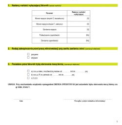
    Please send me if any of you have settings for the value that turns off the inverter - page 6 of the Energa operator appendix.

    My sofar 5.5KTL-X inverter

    6 KWp photovoltaic installation - diagram and connection method

    best regards
    Luke

Topic summary

The discussion revolves around the installation of a 6 kWp photovoltaic system, specifically addressing the connection methods and necessary protections for compliance with local regulations. The user has purchased a kit consisting of 22 Just Solar 285W panels and a Growatt 3-phase 6000W inverter. Key points include the need for overcurrent protection on both the DC and AC sides, the inclusion of a surge arrester, and the requirement for a ZE energy meter in the installation diagram. Participants emphasize the importance of proper grounding and equipotentialization between the photovoltaic system and the existing electrical installation. There are also discussions about the documentation required for connecting to the grid, including the necessity of a signed diagram and the potential need for building qualifications. The conversation highlights various technical aspects, including the use of fuses, the configuration of strings, and the implications of regulations for self-installers.
Summary generated by the language model.
ADVERTISEMENT