logo elektroda
logo elektroda
X
logo elektroda

ESP32, battery back-up and digital potentiometer amplifier control

czarny8322 2970 33
ADVERTISEMENT
Treść została przetłumaczona polish » english Zobacz oryginalną wersję tematu
  • #31 18486354
    czarny8322
    Level 11  
    Thank you khoam;) .
    You have helped me a lot:) Another problem eliminated:

    ESP32 is flashing and I can see the peripherals over I2C.

    Another problem appeared on the horizon. In addition to the radio, the ESP is supposed to control the NIXIE tubes.
    After connecting the power supply, the 470K resistors - R2, R6, R9, R12 that control the cathodes - were literally fried. Currently a voltage of 170V is deposited on them.

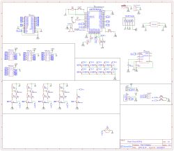
    This is a well known and duplicated schematic on mmbta42/92 transistors. Can you perhaps see the cause of the burned resistors?
    ESP32, battery back-up and digital potentiometer amplifier control
    .
  • ADVERTISEMENT
  • Helpful post
    #32 18486585
    TvWidget
    Level 38  
    czarny8322 wrote:
    After connecting the power supply, the 470K resistors - R2, R6, R9, R12 controlling the cathodes - were literally fried. Currently a voltage of 170V is deposited on them.
    .
    170²/470000=61mW
    My bet is that these are not 470k resistors.
  • ADVERTISEMENT
  • #33 18486775
    khoam
    Level 42  
    czarny8322 wrote:
    After connecting the power supply, the 470K resistors - R2, R6, R9, R12 controlling the cathodes - were literally fried. Currently a voltage of 170V is deposited on them.
    .
    What voltage value does HV represent? This measurement is probably, already after these resistors have been burned? ;)
  • #34 18490388
    czarny8322
    Level 11  
    You were right - it couldn't be 470K - I must have soldered 470 Ohms in a hurry....
    Yes, that 170V value was already after the resistors were evaporated.

    I've eliminated most of the problems for now, unfortunately the PCB is up for rework, but at least it's going in the right direction.

    Many thanks for all the advice.
  • Topic summary

    The discussion revolves around building a radio using an ESP32 microcontroller with battery backup and controlling a PAM8403 amplifier via a digital potentiometer (X9C103). Key concerns include the feasibility of the battery backup circuit, voltage compatibility between the ESP32 (3.3V) and the X9C103 (5V), and potential errors in the schematic. Participants highlight the need for logic level conversion, the limitations of using a CR2032 battery for powering the ESP32, and the importance of deep sleep mode for power management. Suggestions include using an external RTC (DS3231MZ+) for timekeeping and exploring alternative power solutions like 18650 batteries. The conversation also touches on issues with I2C connections and resistor specifications in the circuit design.
    Summary generated by the language model.
    ADVERTISEMENT