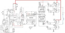
I will try later thank you. I've changed again the two 2110 and now I have square but only on two IRGPs. On your picture, is it normal that only 2 IRGPs are soldered ?
Can you show me the signals you have on the 4 gates of 4 IRGPs please ?
Thanks again
Added after 11 [hours] 25 [minutes]:
Sorry, I did not see that your measurements were on the four gates. I've unsoldered all IRGPs - should I solder at least two IRGPs as on your picture to mes the gate voltage ?
My bulb is 160W (actually, two bulbs : 100W + 60W).
Added after 1 [hours] 20 [minutes]:
So here is out A and out B signals
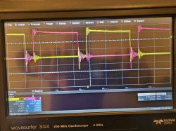
voltage measured :
SG 3525 :
- pin 16 = 5v
- pin 13 = 17v
pin 10 = 0,11v
pin 9 = 5,69v
IRGPs see picture :
top IRGP (gate D753/R753) : squared signal in yellow (following Lo signal of IR2110 U4 )
bottom IRGP (gate DD750 R750): opposite squared signal in pink (following Lo signal of IR2110 U5) :
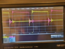
but on the two gates of the two others IRGP (from HO of the two 2110), I have a constant 14v voltage.
Once again, the 4 IRGPs are unsoldered during these measurements.
Any advice ?
Added after 7 [hours] 9 [minutes]:
Hi - I've modified the schema :
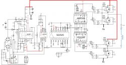
And after having soldered only Q192 and Q194, I had the following signals :
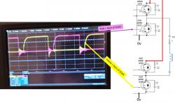
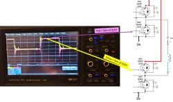
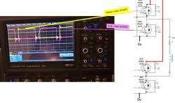
So before soldering Q 191 and Q193, I wonder if those signals seem to you ok as they are not very proper square signals, with bouncing at the rising edge of Q191 and Q193, but maybe it's because Q 191 and Q193 are not soldered and so no C179 and C177 filtering cap.
What do you think ?

