logo elektroda
logo elektroda
X
logo elektroda

T.amp TSA 4-1300 Power Amplifier Issue: Not Turning On, Red Diode Flashing, No Visible Damage

Matek920605 70434 346
ADVERTISEMENT
Treść została przetłumaczona polish » english Zobacz oryginalną wersję tematu
  • #301 21080577
    Robercikxxx
    Level 15  
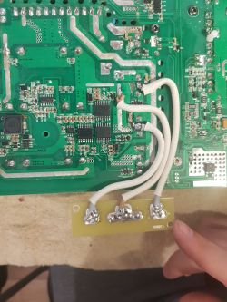
    Here you go. If you put fuses on the top transistors then if a transistor fails there will be no blowout just the fuse will burn out. Close-up of a circuit board with white wires soldered onto it. .
  • ADVERTISEMENT
  • #302 21081513
    zbyszekdymny
    Level 12  

    Factually a good idea with these fuses, there will always be less damage if transistors fly. And it is possible to know what value of fuse the colleague has chosen? And what characteristics, delayed or fast? I'm only going to use this trick for the next repair, because I gave the amplifier to the customer.

  • ADVERTISEMENT
  • #304 21082226
    zbyszekdymny
    Level 12  

    Thank you, my colleague, for your help. Points have flown to your account. Regards
  • #305 21290239
    9r5n0nd026
    Level 1  
    Hello, I'm new on this forum... I have a problem with my TSA4-1300 amp, with a start failure. I had read the topic but most of the explanations are hard to understand. I'm not an electronic engineer and my English is not so good ...

    Few days ago, my amp didn't want to start, today I opened it to look inside but I didn't see something wrong. Today it randomly started 3 times and I can't explain why.

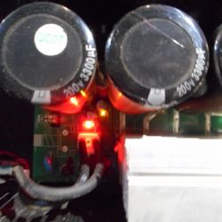
    I have 2 LEDs that turn on when it's in failure, the D201 in red, and the D281 in green

    Close-up of the interior of a TSA4-1300 amplifier with visible capacitors and LED lights.

    I have only a voltage meter to make measurements and the only measurement I took is AC 220V between CN33 and CN21 and AC 125V between CN10 and CN11

    Do you think it could be the transformer or it could be another part ?

    Thanks for your help
  • ADVERTISEMENT
  • #306 21293625
    Kawaiito
    Level 4  
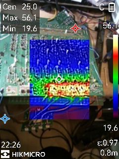
    Thermal image of TSA4-1300 amplifier showing temperature variations.


    i have a problem with the 30V from the 15+/-15 i desolder the LM24 so i mean the problem is behind him but the voltage drops to 22V and this area goe heat... all OP AMPS has the 15V on VCC and the symmetrical 15/15- works .. is to too much smd parts to find the problem. i have the solder channel 1-3 so problem was channel 1 at first there the igbt goes to fire
  • #307 21293947
    Robercikxxx
    Level 15  
    The Lm7824 only powers the relays and possibly the temperature sensors. I can't remember that anymore. Take a lab power supply, set it to 24V 0.5A and plug into the output of the lm7824 and of course solder out the stabiliser.
  • #308 21310371
    Kawaiito
    Level 4  
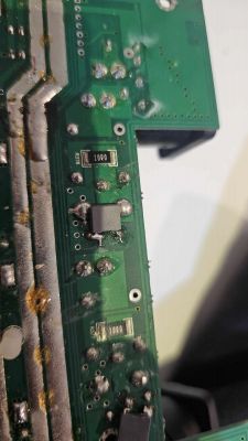
    I have a second 4-1300 but I mean it is an older version … so the 15VAC is only for the opamps Close-up of an old version of the 4-1300 circuit board, showing electrical traces and components. View of a circuit board with multiple traces and electronic components. Printed circuit board with electronic components. Circuit board with multiple electronic components on a green background.
  • #309 21344509
    jeanbernardsers
    Level 5  
    Hi everyone. I suggest my power transformer is down as I can't see any DC 15v. Does anyone know the wiring of the main transo pins?
    Thanks a lot for your help
  • #310 21345139
    jeanbernardsers
    Level 5  
    Hi again
    Can somebody tell me which part gives VCC to SG3525 (pin 15), IR2110S (pin 3), LM339 (pin 3), LM555 (pin 8) please? I have high voltage on CO8 ... but no VCC on ICs and no 15V on the transformer ...
    Thank you very much for your help
  • #311 21348900
    Robercikxxx
    Level 15  
    In yellow you have marked the circuit that is responsible for supplying the +17V to the inverter circuits.
    In red you have marked circuits that can be faulty and make a short circuit and for this you have no supply voltage.

    Circuit board with components marked in red and yellow. .
  • #312 21349013
    jeanbernardsers
    Level 5  
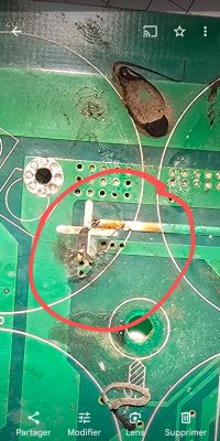
    Thanks a lot for your help and your fast reply - I found the problem: it was a broken wire under a 3300 µF capacitor (see picture).
    Now the red and yellow leds (on the board) are on (no flashing) when I power on but no led light on the front panel of the amp, no relay on, no fan on .. Got to check from where the problem comes from. I started with LM555 and I have 15v on pin 8 (VCC), pin 3 output and 10v on pin 5 (control voltage) but no oscillator wave from output - any idea?
    PS also changes 4 IRGP, the triac, two 2110S, LM339, LM555 and R 473, 474, 475V and 476.
    Thanks in advance Damaged circuit board with a broken conductor.

    Added after 3 [hours] 27 [minutes]:

    Add on : I have no voltage of second part of the transfo (where I should have 15v AC) - can somebody tell me from where it could come from ? I will unsolder the 10000µF caps to have a look ...
  • ADVERTISEMENT
  • #313 21350022
    Robercikxxx
    Level 15  
    Where do you measure this voltage ?
  • #314 21350415
    jeanbernardsers
    Level 5  
    Good news : I can see alternative signals on SG 3525 pin 11 and 14 (see picture). The yellow led turns off after a while when those signals appear (and only the red led remains on).
    But I have no voltage on any pin of the transfo (see picture). Close-up of a circuit board with a pink rectangle highlighting and the text no voltage between pins. Oscilloscope screen showing signals on pins 11 and 14 of the SG3525 with annotations.
  • #315 21360681
    Ziemowit1973
    Level 13  
    jeanbernardsers wrote:
    I see alternative signals on SG 3525 pin 11 and 14 (see photo)


    Explore further
    The SG 3525 is the PWM control bone
    The two ir2110 are current drayers which are controlled from the SG 3525 and they are always replaceable in this amplifier. They directly control the gates of the 4 IRGP 4066D keys.
    If you connect an oscilloscope and want to observe both waveforms at the same time, as shown in the picture, be careful not to short circuit the common ground !!! i burned one example like this :(
    ---
    Around the key transistors all those diodes, resistors, capacitors are also mostly ALWAYS to be replaced - check them meticulously !!!
    ----
    and remember - the power supply in these amplifiers fails 90% of the time due to a short circuit in the power amplifier - in the power amplifier you have more than 40 transistors to check - check them scrupulously ALL - if you don't do that and turn the amp on it will blow up again !!!
    ---
    First run the amp through e.g. a 1000 watt heater - this will protect you from a possible explosion !!! i even do tests without load this way :)
    Good luck :) .
  • #316 21360689
    Robercikxxx
    Level 15  
    You forgot to add that in order to have a top transistor waveform on the Ir2110 circuit the bottom LH transistor must be soldered out of course with working resistors and diodes at the transistor. Merry Christmas to you.
  • #317 21360867
    jeanbernardsers
    Level 5  
    >>21360681 >>21360681 >>21360681 Thank you very much Ziemovit for your reply - will try this. I wish you a merry christmas

    Added after 1 [minutes]:

    >>21360689 Thanks a lot >>21360689 Thanks a lot Robercikxxx for your reply. Will do it also. Best wishes to you and your family
  • #318 21363951
    Ziemowit1973
    Level 13  
    I did a bit of analysis of the parts this amplifier is made of and we have:

    Power supply is 4x IRGP4066D - Nominal Current 75A
    Continuous Collector Current at 100st.cel. We have 90A .
    --
    We have for both branches 2 x 75A x 320V = THEORETIC 48 kWat power !!!
    Power supply - them someone will say it's not made with stock.

    The amp on one channel is:

    5x NJW0302G (PNP)
    5x NJW0281G (NPN)
    These transistors get short-circuited which is the most common cause of failure for this amplifier.
    --
    These are professional audio transistors with maximum linear characteristics
    Collector Current - Continuous 15A
    Collector Current - Peak 30A
    Assume 10A per transistor continuous current:
    10A x 10pcs x 170V = 17 kW power.
    Theoretical with spare calculation 17 kW continuous power we compare to load on 4 ohms:
    --
    170V x 170V / 4 Ohms = 7.225 kW PMPO at full drive under clip !!!
    For sine wave RMS power we have about 3.6 kW .
    For music (CF 10dB) the RMS is approximately 0.7 kW power
    So the end can theoretically withstand 17 kW and musically is loaded with RMS no more as 1 kW at PMPO 7,3 kW a4a9e232222e .
    --
    I can count it from the other side:
    We are counting the current peak - i.e. that moment where the transistors conduct full current - amplifier at a clip !!!
    170V / 4 Ohms = 42,5A -- and these 42 Amps are broken down into 5 pieces of transistors where each can withstand continuous current 15 A !!! together on one branch we have the strength 75 A .
    Collector Current - Peak for this transistor is a reminder 30A so in theory 150A in peak it could hold - so we have 42,5A VS 150A
    -
    [b]We have one more parameter for the NJW0302G and NJW0281G transistors.

    Total Power Dissipation - The maximum power loss that a transistor can safely dissipate in the form of heat when operating under certain conditions.
    For 25 deg. we have 150W .
    For 80 st we have 80W .
    On 10 pieces, therefore, it is possible to dissipate 800W heat when, of course, we heat the amplifier to these 80 degrees.
    Is this safe ? well not really - here I think is the bug because of which these amps explode :) .
    What we know:
    1 - I can dissipate 800W when I have a heated amplifier.
    2 - The amp on 4 ohms when playing music under a clip will send about 700W power . RMS which would suggest that no more than 700W of heat remains dissipated on the heat sinks of one channel, so in total we have about 2kW heat to be dissipated from the four channels plus power supply heat !!!
    Draw your own conclusions.

    Finally, why is the amplifier burning ????
    I think that it overheats when you load it with four speakers of 4 ohms each and then the explosion is already inevitable :(
    "Cure"
    It will be safe if we connect only 8 ohm loudspeakers :) then the power drops admittedly by half but thus we have 50% less heat to dissipate from the cabinet :) .

    Greetings[/b].
  • #319 21364098
    398216 Usunięty
    Level 43  
    Ziemowit1973 wrote:
    Power supply - them someone will say is not made with a spare.
    .
    The power supply is not just the diodes.... It also matters what and what power is in front of them....
    Ziemowit1973 wrote:
    Assume 10A per transistor continuous current:

    And in what range of collector current does it operate linearly? These parameters (15A nom and 30 peak) are the parameters for full open in addition under certain conditions - temperature, time etc.
    As for the rest of your calculations, I have the impression that you are getting too excited about numbers without going into what I wrote above - it is one thing to have limit parameters and another to have operating parameters. In addition, it should be remembered that the majority of electronic components are manufactured in China and there the parameters can be whatever you want them to be and what a component can actually withstand is a completely different matter.
    So that one,... More reserve to what you read and more thinking in the very understanding of what you read....
    And by the way - Happy New Year. :)
  • #320 21370408
    jeanbernardsers
    Level 5  
    Hi I had to change again 2 irgp, lm 339 and 555, diodes, and two 2110 after having down short circuit but now no more signal coming from pins 14 and 11 from sg3525. The problème is that I have 5v on pin 10 (shutdown) of sg3525, Even after having changed lm555. All diodes seem ok. Any suggestions ? Does anyone know which is responsible of pin 3 voltage of lm555 ? Thanks in advance and happy new year.
  • #321 21370456
    Robercikxxx
    Level 15  
    Put the original lm339 and Ne555 back in, they were never damaged. I wish you a happy New Year.
  • #322 21370632
    jeanbernardsers
    Level 5  
    Thanks but I think I trashed them then I replaced them with new ones
  • #323 21375612
    gaspixx
    Level 3  
    Hello all,

    I just got this amplifier in non-working condition, planned to repair it and use for mid-range speakers (100-2000Hz / 4x800W / 8ohm). Later I found a lot of negative feedback on this amplifier. Anyway, I will try to repair it and use it for this purpose.
    Thanks to this forum I saw a lot of important information about repair. Started checking the components. Based on the previous owner, the amplifier was working and after some time goes into protect mode. I didn’t start it yet due to the possible burning of the power supply. I first checked for short circuit briefly and only one possible short I can see on the rectifier bridge, but I need to desolder the complete heat sink to see if this is a real short or only the coil impedance. What I can see is some ‘upgrade’ - somebody soldered at the output parallel to the original 22nF MKT film capacitors another 4 capacitors 10nf/250V – do you know what can be the purpose? Keep them or better remove to original state?

    Circuit board with visible components like resistors and a rectifier bridge.

    I plan to check the semiconductors and resistors/capacitors mentioned in this forum first, then start it with 15VAC/24VAC external symmetrical transformer and check the functionality of all 4 channels. Next I will add also two 8FA fuses, move power resistors from the front VU panel from the front to the bottom side of the PCB to prevent issues with heat on this panel. Connect the grounding points directly with wire. I will probably also change the working components in PSU (IR2110S, SG3525, gate resistors and capacitors…) – just to be sure. Is there anything else to upgrade this board to make it more stable?

    Thank you
  • #324 21376072
    Ziemowit1973
    Level 13  
    >>21375612 .

    Robercikxxx wrote:
    Please go ahead. If you put fuses on the top transistors then if a transistor fails there will be no blowout just the fuse will burn out. Close-up of a circuit board with white wires soldered onto it.
    .

    gaspixx
    Symmetrical power supply - you will work like a wild boar !!! give it to yourself.

    1 - Foreman and not better for you to cut the tracks as in this picture.
    2 - run the power supply checking the waveforms with an oscilloscope on the gates of the main transistors on the power supply and be careful if you want to observe both waveforms at the same time because you will make a short circuit with the common ground and you're ready to explode - I had like that :( .
    3 - then you MUST measure absolutely all the parts around the power supply key transistors - all those faders, diodes, resistors etc. there are if I remember correctly 6 pieces per transistor, 24 components to check.
    4 - then you check all the rectifier bridges for short circuit and transition - you have 3 of them.
    5 - then you check all the transistors that are on the terminals on those long heatsinks for short and transitions - this is easy because you have 4 channels so you have something to compare them to - there are over 40 of them.
    5 - then finally the commissioning - I put a 1 kW heater in series !!! without this it is very important not to even think about starting up.
    6 - then with the farelka you test by fastening on the load instead of the column a simple 25 watt 250V bulb and go over the clip - here and only here you can use a sine wave.
    7 - once you have succeeded in doing this you then put the flare on 2kW of power fasten the column and you can play quietly one at a time on all the channels to see if it will play at all.
    8 - once you've got that going you do a normal test without the flare - 500 watt resistor. 8 ohms to the output (not 4 because you're asking for an explosion) and you go to the clip on a CF waveform of about 8 dB - NO SINUSOID because you're asking for another explosion, this amp is for music not sine wave, the waveform I can give you as an MP3 :) I made it myself :) .
    9 - once you get it right you jump to the ceiling with joy screaming hooray I did it !!! :) :) :) :) :) :)
    ---
    I did it this way :) thanks to the whole forum for the knowledge shown here
  • #325 21381808
    gaspixx
    Level 3  
    Hello Ziemowit1973, all,

    thank you, another couple of questions:
    -is 24VAC / 2x10W enough for first test? or do I need to look for more powerful transformer?
    -did you already tried some working replacement for IRGP4066, GBU2506SF (these are not available on standard suppliers like farnell, ecker...)
    -somebody before soldered at the output of this amplifier parallel to the original 22nF MKT film capacitors another 4 capacitors 10nf/250V (one per channel)– do you know what can be the purpose? Keep them or better remove to original state? Picture is in the topic above.

    Martin
  • #326 21383973
    aaanteka
    Level 42  
    zbyszekdymny wrote:
    Factually a good idea with these fuses,
    .
    Not just not a good idea, but a terrible idea , especially in this particular solution. How do we power the final stage, gentlemen?
  • #327 21383979
    Q-mac
    Level 27  
    aaanteka wrote:
    zbyszekdymny wrote:
    Factually a good idea with these fuses,
    .
    Not just not a good , but a terrible idea , especially in this particular solution. How do we have you guys powering up the final stage,
    .

    And where do we have the proposed fuses ?
  • #328 21383981
    aaanteka
    Level 42  
    A few posts above and a post above repetition. :) .
  • #329 21384006
    Q-mac
    Level 27  
    I see you need to be more literal...

    Since the proposed fuses are to be installed in the primary circuit power inverter, what effect does this have on the power supply to the final stage ? Apart from the obvious one - the loss of power supply to them.
  • #330 21384009
    Robercikxxx
    Level 15  
    What do you mean by this question , how is the final stage powered ? What does this have to do with fuses ?

Topic summary

The T.amp TSA 4-1300 power amplifier exhibits a failure to power on, with a flashing red diode near the capacitors and no visible physical damage. Investigation revealed multiple damaged IRGP4066D IGBT transistors on the primary side inverter, along with damaged power transistors (NJW0302GC), MOSFETs (GP105N15M), rectifier bridges (GBJ3006SF, 2506SF), and driver ICs (IR2110S, SG3525A). The amplifier uses a full-bridge power supply topology operating around 85-100 kHz with multiple symmetrical voltage rails (+/-15V, +/-40V, +/-60V, +/-90V, +/-160V) for preamplifier and power amplifier stages. The power supply design lacks galvanic isolation, current limiting, and effective overload protection, leading to frequent IGBT and associated component failures. SMD components such as EF8 and T4/H5 diodes (likely Schottky and Zener types) near the inverter and driver circuits are critical and often damaged. The triac (BTA41-600B) controlling AC mains to the rectifier bridge is also a common failure point. Repair attempts require replacing IGBTs, driver ICs, rectifiers, and passive components, but without a schematic or service manual, troubleshooting is challenging. Oscilloscope measurements of PWM signals and gate drive waveforms are essential for diagnosing dead time and control issues. Some users suggest replacing the entire power supply with a custom design due to the amplifier’s complex and failure-prone power stage. The amplifier chassis serves as a ground connection, which must be properly connected during bench testing. Auxiliary power supplies (e.g., 2x12V AC transformers) are used to test amplifier channels independently. Despite extensive repairs, issues such as persistent fault LEDs, relay non-activation, and channel-specific transistor failures remain common. The amplifier is considered difficult to service due to integrated power and control boards, lack of documentation, and complex SMD circuitry. The original design is reportedly based on the Chinese Leicozic DP41200 amplifier. Community consensus highlights the need for careful component verification, replacement of damaged SMD diodes and resistors, and cautious startup procedures using current-limited power supplies or light bulbs to prevent repeated damage.
Summary generated by the language model.
ADVERTISEMENT